Installation
12 S&C Instruction Sheet 716-500
STEP 3. For circuit-switchers rated 69 kV through 138 kV:
Attach the lifting angles to the circuit-switcher
base using ½-13 x 1¼ hex-head galvanized steel cap
screws, at washers, and nuts furnished. See
Figure 5. Securely tighten the cap screws, and then
attach four suitable lifting slings to the lifting an-
gles. Unbolt the base from the shipping skids and
lift the base—with interrupters and insulating
support columns attached—on top of the mounting
pedestals as shown on the catalog drawing. Avoid
sudden starts and stops. Verify that the SWITCH-
POSITION indicator on the base is visible on the
desired side. (This is also the side on which the
operator door will open.) See Figure 5.
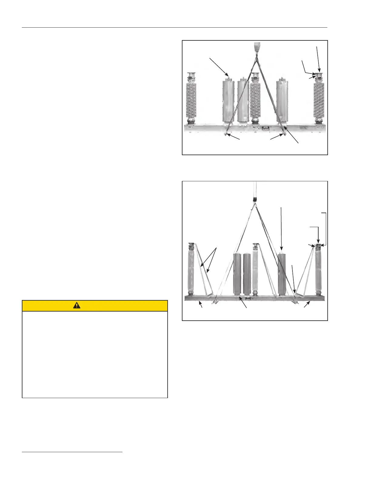
For Circuit-Switchers rated 161 kV and 230 kV:
Attach four suitable lifting slings to the eyebolts
connected to the two inboard shipping channels.
See Figure 6. Unbolt all four shipping channels
from the shipping supports. Also unbolt and dis-
card the two outboard shipping channels from the
circuit-switcher base, as shown in Figure 6, but
retain the associated ½-13 x 1¾ galvanized steel
cap screws, flat washers, and nuts. Do not unbolt
the two inboard shipping channels from the circuit-
switcher base. Now, lift the base—with interrupters
and insulating support columns attached (including
the support angles and support braces for the insu-
lating support columns)—on top of the mounting
pedestals, as shown on the catalog drawing. Avoid
sudden starts and stops. Verify that the SWITCH-
POSITION indicator on the base is visible on the
desired side. (This is also the side on which the
operator door will open.) See Figure 6.
Remove and discard the three sets of support
angles and their associated hardware. Also remove
and discard the three support braces and their asso-
ciated hardware. Leave the shipping covers on top
of the insulating support column transition boxes.
CAUTION
The operator directly drives the interrupters open and
closed through a high-speed power train leading from
the top of the operator, through a horizontal interphase
linkage enclosed in a steel-sheathed box-type base, to
reciprocating-action insulated operating rods that pass
through the center of the insulating support columns.
Permanently lubricated bearings are used throughout
the power train. The high-speed base has been fully
pre-assembled and adjusted at the factory. DO NOT
disassemble the high-speed base or high-speed
power train. Damage to the high-speed base and
personal injury may result.
Interrupter lifting
bracket
Shipping cover
Access
cover
Transition box
Lifting angle
Interrupter shipping bracket
and clamps
Figure 5. Hoist the high-speed base using a crane, 69-kV through
138-kV circuit-switchers.
Support angle
Interrupter lifting bracket
Access
cover
Shipping
cover
Transition
box
Support
brace
Outboard shipping
channel (removed)
Outboard shipping
channel (removed)
Interrupter shipping
bracket and clamps
Figure 6. Hoist the high-speed base using a crane, 161-kV and
230-kV circuit-switchers.