Installation
S&C Instruction Sheet 716-500 13
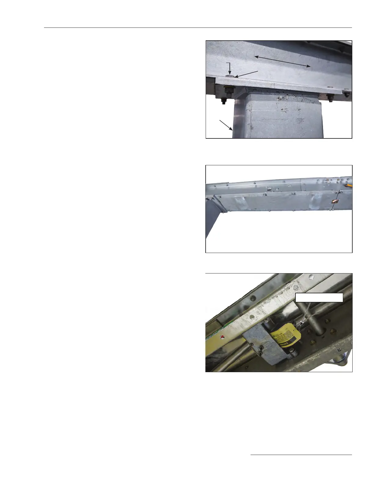
Bolts
Shims
(if required)
Pedestal
High-speed base
Figure 7. Shim the high-speed base for gaps of more than ⅛-inch
(3.18 mm).
Figure 8. Remove bottom plates from high-speed base.
Pin and cotter pin
Figure 9. Remove the ¾-inch stainless-steel pin and cotter pin
from the interphase-drive lever inside the high-speed base.
STEP 4. Loosely bolt the high-speed base to the mounting
pedestals using the ⅝-11 × 2¼ hex-head galvanized
steel cap screws, at washers, and self-
locking hex nuts furnished. Lubricate the bolts to
facilitate tightening, and then, using a level, verify
that the high-speed base is horizontal, both length-
wise and sideways. Adjust the lower set of anchor
bolt nuts at the pedestals to achieve level.
STEP 5. Securely bolt the high-speed base to the mounting
pedestals. If necessary, install shims between the
high-speed base and the pedestals to compensate
for any gaps greater than ⅛-inch between the
mating surfaces. See Figure 7.
Tighten the bolts on the high-speed base to
75ft./lbs.
STEP 6. Check the lower set of anchor-bolt nuts at each
mounting pedestal to verify that all nuts are in
contact with the bottom of the pedestal. Hand-
tighten the anchor-bolt nuts as necessary, and then
securely tighten the upper set of anchor-bolt nuts at
each mounting pedestal. See Figure 3 on page 11.
STEP 7. For circuit-switchers rated 69 kV through 138 kV:
Remove and discard the lifting angles, but retain
the associated ½-13 × 1¼ galvanized steel cap
screws, at washers, and nuts. See Figure 5 on
page12.
For circuit-switchers rated 161 kV and 230 kV:
Remove and discard the inboard shipping channels,
but retain the associated ½-13 × 1¾ galvanized steel
cap screws, flat washers, and nuts. See Figure 6
on page 12.
Remove the remaining hardware used to attach
the bottom plates adjacent to the operator support
tube mounting plate. See Figure 8. Put the bottom
plates and hardware aside on a clean surface. Also
remove the ¾-inch stainless-steel pin and cotter
pin from the interphase drive lever enclosed in the
high-speed base. See Figure 9. Retain these pins for
re-use in Step 17 on page 19.