Installation
S&C Instruction Sheet 716-500 15
STEP 10. Prepare the interrupter for attachment to its
insulating support column as follows:
(a) Remove and discard the two #10-32 screws that
connect the operating-rod holding bracket (marked
with a black/yellow striped label) for shipment. See
Figure 13.
CAUTION
Keep hands clear of the operating rod when remov-
ing the shipping bracket. The insulated operating rod is
under pressure. Removal of the bracket may result in the
operating rod quickly moving down approximately 3/8-
inch. Injury to the hands may result.
(b) Pull the holding bracket to move the operating rod
to its fully Open position. See Figure 13.
(c) Remove the connecting pin used to attach the hold-
ing bracket to the coupling. Retain the connecting
pin for re-use in Step 11(f). See Figure 13. Discard
the holding brackets.
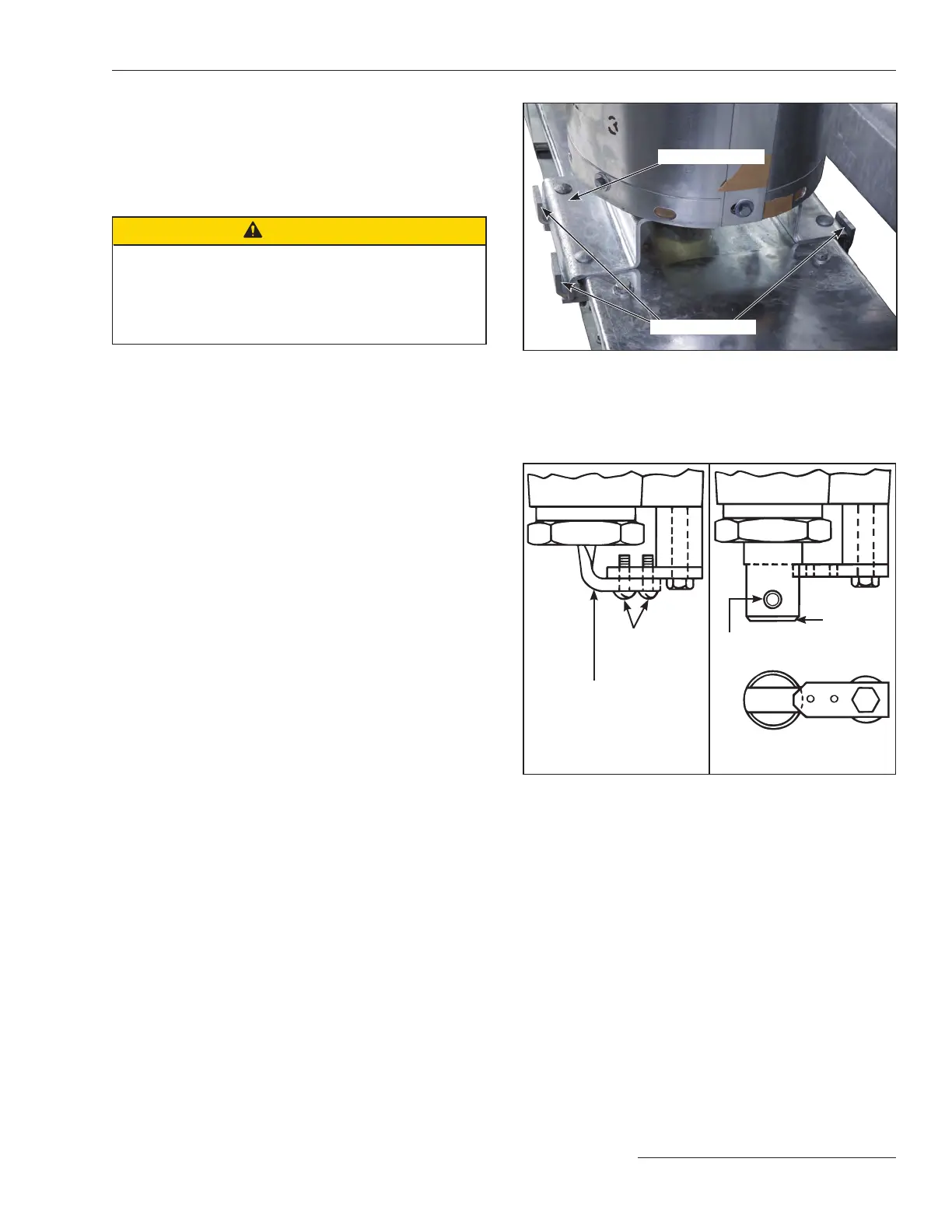
Shipping bracket
Shipping clamps
Figure 12. Attach a lifting sling to one of the interrupters. Remove
the hardware securing the shipping clamps to the base. Lift the
interrupter off of the base. Remove the hardware securing the
clamp to the interrupter. Retain the hardware. Discard the ship-
ping bracket.
Operating-rod holding
bracket (marked with a black/
yellow striped label)
Connecting pin
#10–32 screws
Operating rod in shipping
position
Coupling
Operating rod in fully open
position
Figure 13. Prepare the interrupter for attachment to the insulat-
ing support column.