Installation
16 S&C Instruction Sheet 716-500
STEP 11. Attach the interrupter to its insulating support
column as follows:
(a) Remove and discard the shipping cover on top of
the transition box. See Figure 11 on page 14, inset.
(b) Thoroughly wire-brush the top of the transition box
and mating surface on the interrupter, and
immediately apply a liberal coating of Burndy
Penetrox® A (available from Burndy Corporation)
or equivalent aluminum-connector compound to
the brushed surfaces.
(c) Remove the four 5∕16-18 × ¾ hex-head stainless-steel
cap screws used to attach the access cover to the
side of the transition box. Remove the cover and
place it and the hardware on a clean surface. See
Figure 11 on page 14. Also remove the cloth bag
containing the hardware that will be used for con-
necting the interrupter coupling to the operating
rod link in Step 11(f).
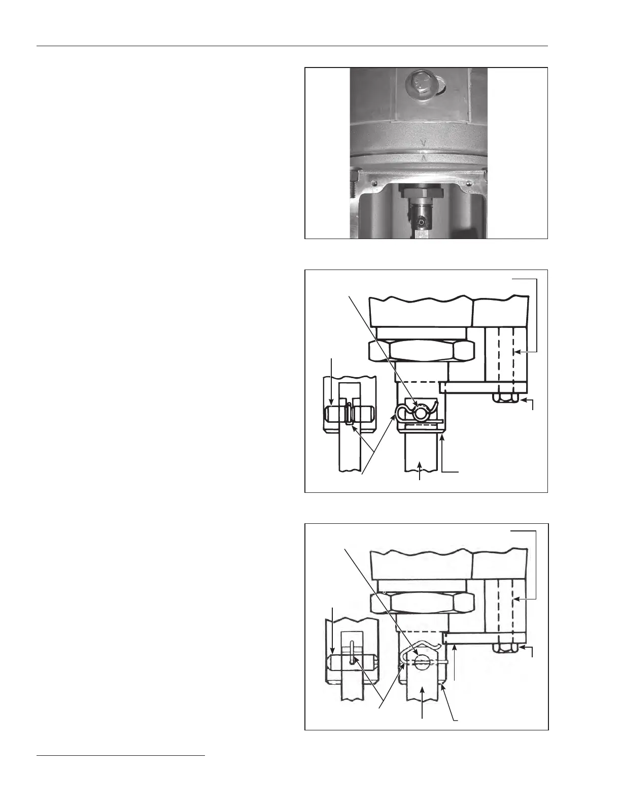
(d) Make certain the positioning mark stamped on the
bottom of the interrupter is aligned with the
position mark stamped on the top of the transition
box. See Figure 14.
(e) Lower the interrupter onto the transition box. One
of the ½-13 stainless steel studs on the interrupter
is longer than the other three to aid in aligning the
interrupter with the transition box. Reattach a
½-inch Belleville washer and a ½-12 stainless steel
hex nut, retained from Step 9, to each of the four
studs. Lubricate the nuts to facilitate tightening.
Tighten each nut securely.
(f) For circuit-switchers rated 69 kV through 138 kV:
Insert the connecting pin retained from Step 10(c)
into the coupling and operating rod link. See
Figure15. It will be necessary to loosen the 5∕16-18 ×
2¼ hex-head stainless steel screw indicated in
Figure 15 and withdraw it approximately ⅛-inch so
the connecting pin can be inserted. Do not remove
the screw at this time. Insert the pin retaining clip
as indicated in Figure 15. Make sure that the clip is
positioned as shown.
For circuit-switchers rated 161 kV through
230kV: Insert the connecting pin retained from Step
10(c) into the coupling and operating rod link. See
Figure 16. It will be necessary to loosen the 5∕16-18
× 2¼ hex-head stainless steel screw indicated in
Figure 16 and withdraw it approximately ⅛-inch, so
the connecting pin can be inserted. Do not remove
the screw at this time. Use a flat-head screwdriver
blade in the slot at the end of the connecting pin to
align with the cross-hole in the operating rod link.
Now, insert the pin retaining clip as indicated in
Figure 16. Make sure the clip is positioned as shown.
(g) Remove and discard the 5∕16-18 × 2¼ hex head
stainless steel screw, stop bracket (marked with a
black/yellow striped label), and spacer (marked
with a black/yellow striped label) illustrated in
Figures 15 and 16.
Figure 14. Align the positioning mark on the interrupter with
the mark on the transition box.
Spacer (marked with a
black/yellow striped label)
Connecting
pin
Pin retaining clip
Operating rod link
Coupling
Stop bracket (marked
with a black/yellow
striped label)
Slot (coincides
with cross hole)
5⁄16 –182¼ hex-head
stainless steel screw
Figure 15. Connect the interrupter to the operating rod link.
(69 through 138 kV)
Connecting
pin
Operating rod link
Coupling
Stop bracket (marked
with a black/yellow
striped label)
5⁄16 –182¼ hex-head
stainless steel screw
Slot (coincides
with cross hole)
Pin retaining clip
Spacer (marked with a
black/yellow striped label)
Figure 16. Connect the interrupter to the operating rod link.
(161kV and 230 kV)