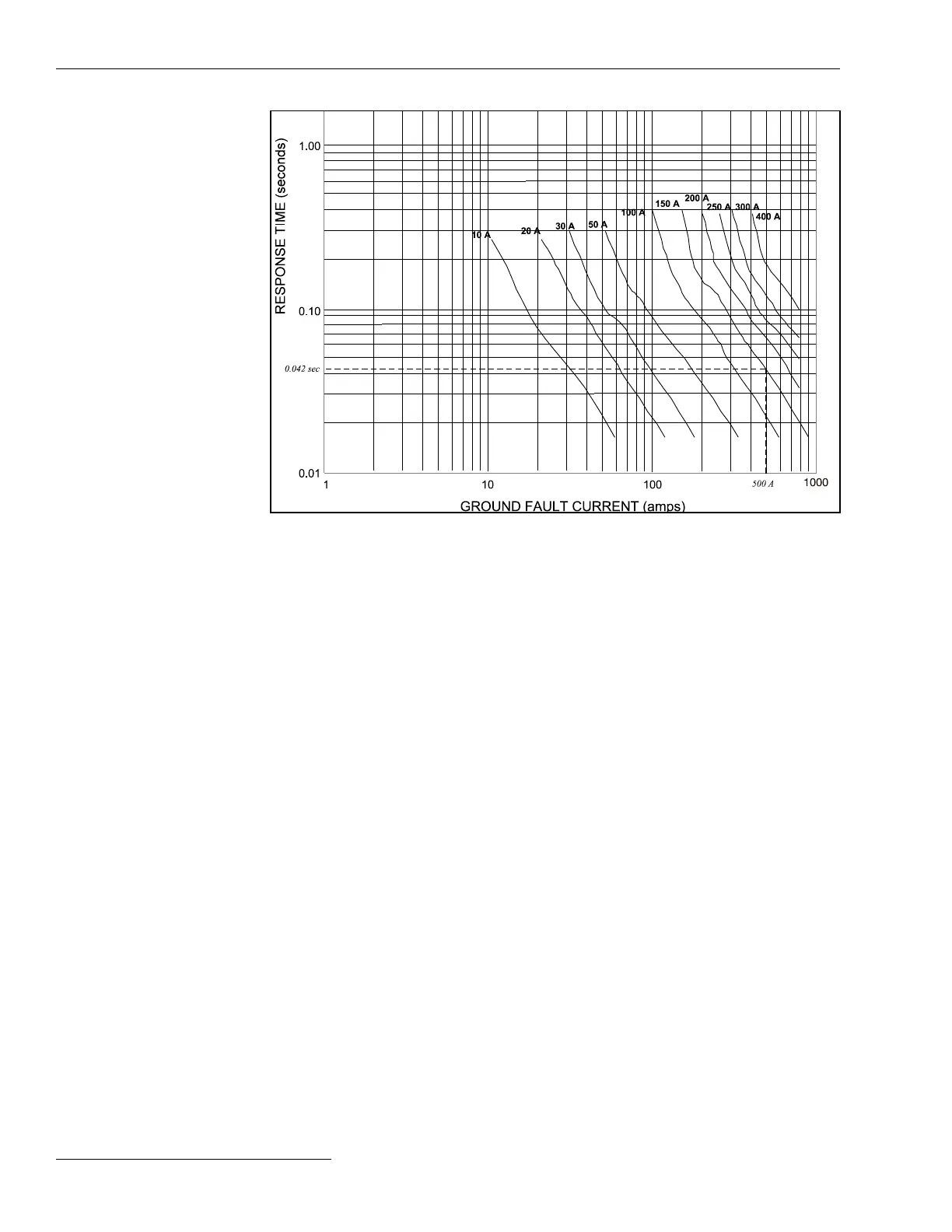
Figure 13. The TCC curve for ground fault detection.
Phase Overcurrent Detection Setup Procedure
To determine the proper setting, we need to look at the source-side protective device phase
TCC curves for a range of fault duty, up to the maximum available phase fault current
at the sectionalizing switch. In general, set the Phase Fault Detection Current Level
setpoint slightly lower than the source-side protective device’s minimum pickup/trip
and the Phase Fault Duration Time Threshold setting slightly faster than the fastest
time the source-side protective device will trip. See Figure 14 on page 31 for an example.
Phase Fault Detection Current Level (RMS Amps)
Set the Phase Fault Detection Current Level to a value equal to 90% of the minimum
pickup/trip of the source-side protective device. The setpoint may be increased to 95%
or higher in situations where an available inrush restraint multiplier is too small to mask
expected inrush currents but the next higher multiplier is too large and may mask fault
currents. (Range: 0-65,530; Step: 10; Default: 800 when current sensor ratio is 600:5;
otherwise, Default: 1600)
Phase Fault Duration Time Threshold (Milliseconds)
Set the Phase Fault Duration Time Threshold to a value equal to or less than the
breaker total clearing time minus the Time Block inrush restraint value, if any, and
minus 19 ms (where 19 ms is the approximate time required for the control to conrm a
fault). The inrush restraint time can be ignored in situations where numerical multipliers
are used (the Time Block value is not used), and the elevated overcurrent level (the
numerical multiplier times the Phase Fault Detection Current Level setting) is less
than the expected minimum phase fault current levels. In situations where the elevated
overcurrent level exceeds the estimated Minimum Phase Fault Current levels, select the
lowest inrush multiplier that will protect against inrush. Minimum Phase Fault Current
levels may be estimated as 60% of end-of-line maximum fault current levels where the
end-of-line is dened as the worst case end-of-line after load has been transferred to the
alternate feed. (Range: 12.50-2,725.00; Step: 6.25; Default: 50)
Switch Control Setup
30 S&C Instruction Sheet 1045-530

 Loading...
