Switch Control Setup
Inrush and Load Pickup Restraint
Inrush and load pickup currents occur when voltage is restored to a distribution circuit
with connected load.
Magnetizing inrush—The magnetizing-inrush current has a short duration, and its
magnitude depends primarily on connected transformer capacity, residual magnetism
in the transformers, and system impedance. Generally accepted inrush for a single
distribution transformer is up to 25x full-load kVA for 0.01 second.
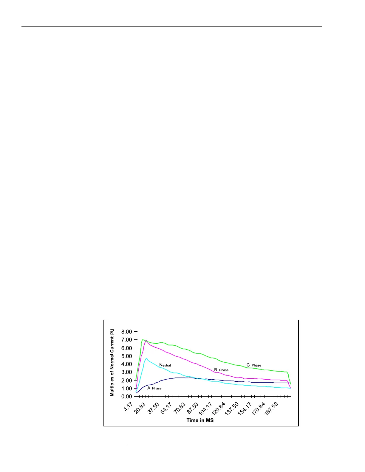
Hot load pickup—The hot-load pickup current occurs when the source breaker trips
and recloses. Its magnitude depends on the magnetizing inrush and the type of connected
load. For example, a momentary power interruption may cause motor controllers to
disconnect their motors, while resistive loads may remain online. See Figure 16.
Cold load pickup—The cold-load pickup current occurs from connected load after an
extended outage. The magnitude depends on the magnetizing inrush and the type and
amount of connected load and the duration of the outage. For example, thermostatically
controlled loads (such as refrigeration, air conditioning, and heating) will increase due
to a loss of diversity. Generally accepted inrush for cold-load pickup is 6x full load for 1
second, 3x full load for 10 seconds, and 2x full load for 100 to 300 seconds.
The 6800 Series switch control invokes inrush restraint whenever three-phase voltage
is lost and one or more phases return. The current inrush restraint time is the amount
of time, in milliseconds, that must elapse after restoration of voltage before the switch
control will respond normally to an overcurrent fault condition. The Phase or Ground
Current Inrush Restraint Multiplier setting determines the switch control response
during this time period.
When using a fast reclose on the source-side breaker, it must remain open long enough
for the control to detect the outage or inrush restraint will not be applied. The time
required for the control to detect a loss of voltage is variable depending on the selection
of the Loss of Voltage Threshold setpoint. For example, the control can detect a loss
of voltage in approximately 11 cycles with a threshold of 60 volts or 14 cycles with a
threshold of 20 volts.
The software has two types of inrush/load pickup restraint: time block and a numerical
multiplier. When the Inrush Restraint Multiplier setpoint is set to the Time Block
setting, the switch control ignores all overcurrent conditions during the restraint time.
When it is a numerical Multiplier Value (2x, 4x, 8x, or 16x), the corresponding Phase or
Ground Fault Detection Current Level setting is temporarily raised by the multiplier
value.
Setup Procedures
Evaluate the magnitude and type of load beyond the switch control, and estimate the
magnitude and duration of the inrush/load pickup current. See Figure 14 on page 31.
Figure 16. Example of hot load pickup inrush currents for a commercial area.
34 S&C Instruction Sheet 1045-530

 Loading...
