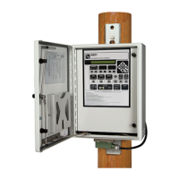
Switch Control Setup
Time Block—Ground (unbalanced) currents are not qualied until the restraint timer
expires. Adjust the Ground Fault Duration Time Threshold and Ground Current
Inrush Restraint Time setpoints to ensure the switch control has enough time after
the time block to detect a ground fault before the feeder breaker operates again.
Multiplier Value—The Ground Fault Detection Current Level is temporarily raised by the
selected multiplier value: 2x, 4x, 8x, or 16x. If the switch control detects currents whose
magnitudes are greater than the elevated level, it starts the Ground Fault Duration
Time Threshold timer. The switch control records a fault when current remains above
fault level and the timer expires.
Set the multiplier to raise the ground-fault current-detection level above the expected
inrush/load pickup levels. Don’t set the multiplier higher than necessary or it may mask
a low-level ground fault. When the inrush multiplier raises the elevated fault-detection
current level to a value that exceeds full scale, the result is the same as a Time Block
setting. Full scale for ground faults is 800 amps.
Note: Actual fault duration may be longer than the duration reported in the historic
log. When the Phase Current Inrush Restraint Multiplier or the Ground Current
Inrush Restraint Multiplier feature is set to the Time Block mode:
• The control does not count the portion of the fault occurring in the Time Block period.
• The Fault Duration Time Threshold begins counting when the Time Block ends.
• Actual fault duration may be longer than the duration reported in the historic log.
• Faults that do not qualify are disregarded.
Suggested Information for Each Switch Location:
Select the phase and ground TCC curves for the source-side protective device:
• Phase and ground source-side protective device minimum pickup/trip (amps)
• Source-side protective device mechanical operation time
• Maximum available phase and ground fault current at each sectionalizing switch
from each source
• Peak normal load current at each sectionalizing switch
• End-of-line phase and ground fault current, for each source
Fault Indicator Reset Strategy
Reset By Timer in Seconds
Reset By Timer in Minutes (default strategy)
Reset By Timer in Hours
When one of the three timer strategies is selected, the Overcurrent Fault indicator
will be automatically reset when all of the conditions required for the Reset When
Fault Clears strategy are met and after a congured time period expires. The Fault
Indicator Reset Timer starts when all three conditions are met. The timer strategy
selected determines the unit of time, and the Fault Indicator Reset Timer setting
species the numerical time.
Note: The switch control will wait until the switch is closed before starting the Fault
Indicator Reset Timer if the switch is not closed when the Sectionalizer Reset Timer
expires.
Reset When Voltage Returns
The Overcurrent Fault indicator will be automatically reset when all of the conditions
required for the Reset When Fault Clears strategy are met and the control has detected
the return of normal three-phase voltage.
Reset Manually
When this strategy is selected, automatic reset of the Overcurrent Fault indicator is
disabled and it must be reset manually. The reset can be selected by a SCADA command,
36 S&C Instruction Sheet 1045-530

 Loading...