S&C Instruction Sheet 1045M-510 23
Installing the Rotating Switch Operator
STEP 17. Press the SET LIMITS button to take the operator out of the Set Limits mode.
The NOT READY LED should not be lit and the switch should be in the Open
state.
STEP 18. Press the SCADA CONTROL CHANGE button to put the switch operator in the
Local state.
STEP 19. Press the CLOSE button. The switch will go to the Closed position and the red
CLOSED LED will illuminate.
STEP 20. Operate the switch several times with the OPEN and CLOSE buttons and
observe switch operation to make sure it fully opens and closes each time.
N OTICE
Any Inspection Required flag from a previous operation will prevent normal fast
operations and cause the NOT READY LED to turn on. To clear the flag, briefly
toggle the ENABLE/DISABLE switch.
If the ERROR DETECTED or NOT READY LED is still on or if the CLOSE/OPEN
LEDs do not operate as described, see Instruction Sheet 1045M-550, “S&C 6801M
Automatic Switch Operators: Troubleshooting.”
Follow these steps to test switch operation:
STEP 1. Make sure the REMOTE/LOCAL switch is set to the Local state and the
AUTOMATIC OPERATION switch is set to the Disabled state.
STEP 2. Following your company’s operating procedures, use the CLOSE or OPEN
button on the faceplate to manually operate the switch. Verify visually that the
switch can be both opened and closed and ensure there is no binding or
mechanical resistance. Verify the switch operator faceplate LED display
correctly indicates when the switch is open and closed.
STEP 3. While the switch is open, check that the gap is big enough to avoid ashover. See
Table 1 for the ANSI standard C37.32-1990 recommendations.
STEP 4. While the switch is closed, check to make sure the switch contacts are completely
engaged. Verify the blades on all phases are against the closed position stop.
This ensures connection with an auxiliary shunt contact is not made. (When
connected, the interrupter would be in a parallel-current path with the blade
and jaw contacts, which is not acceptable.) If the switch contacts are not
completely closed, repeat the Set Limits procedure. If this does not correct the
problem, adjust the tap position on the load resistor to increase the closing
force. See “Adjusting the Tap Position on the Load Resistor” on page 24.
STEP 5. Repeat until satised that the switch is opening and closing properly.
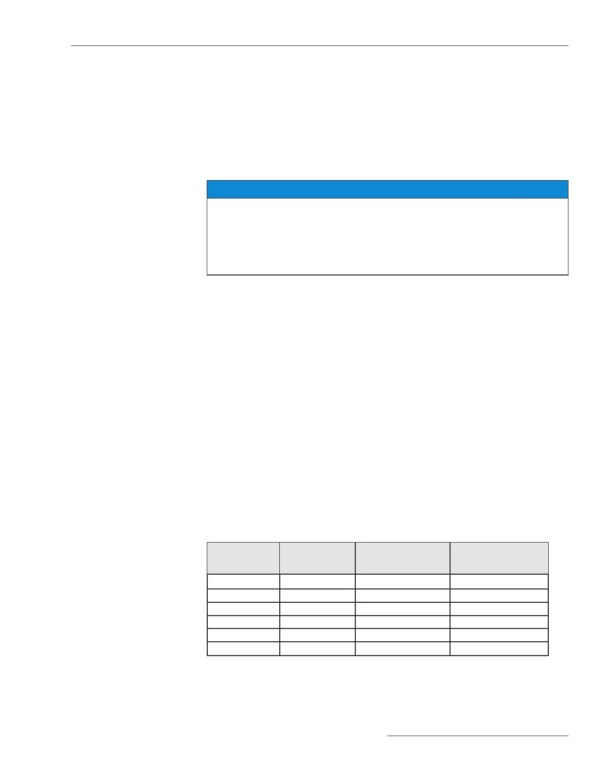
Table 1. Open Gap Distances, ANSI Standard C37.32—1990
Switch Rated
Voltage
(kV, max.)
BIL Rating
(kV)
Recommended Open
Gap
(inches)
Flash Over
Distance
(inches)
8.3 95 7 (178 mm) 6 (152 mm)
15.5 110 10 (254 mm) 7 (178 mm)
25.8 150 12 (305 mm) 10 (254 mm)
38.0 200 18 (457 mm) 13 (330 mm)
48.3 250 22 (559 mm) 17 (432 mm)
72.5 350 32 (813 mm) 25 (635 mm)
Testing Switch
Operation