10 S&C Instruction Sheet 719-500
Installation
Connecting the Switch Operator to the
Circuit-Switcher Vertical Operating Shaft
Complete the following steps to connect the switch operator
to the vertical operating shaft on the circuit-switcher:
STEP 1�
Lift the switch operator as shown in the
“Handling” section on page 6. Then, mount the
switch operator to the structure as indicated on
the erection drawing.
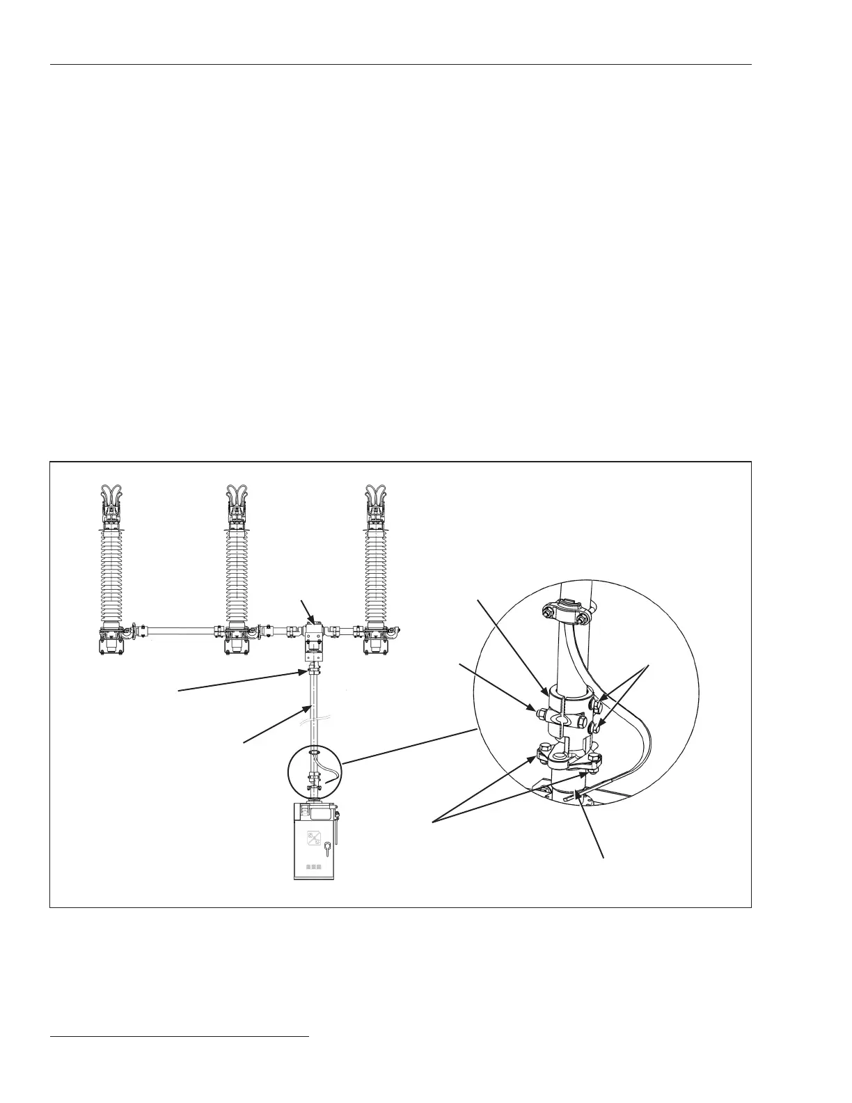
STEP 2� Attach a exible coupling to the output shaft of
the switch operator. See Figure 2 on page 8 and
Figure 4. Thread the attachment bolts through
the flexible coupling plate and through the
coupling ange on the output shaft. Tighten the
bolts to draw the exible plate ush against the
ange; this will deform the threads in the exible
plate, resulting in a binding, nonslip connection.
Install and tighten the self-locking nuts. Do not
use lockwashers with the attachment bolts.
STEP 3�
Remove the clamp bolts and set aside the detach-
able half of the exible coupling.
STEP 4�
Make sure the cutting tips of the piercing set
screws do not protrude through the body of the
exible coupling on the switch operator output
shaft and the exible coupling attached to the
shaft extending from the gearbox on the circuit-
switcher pole-unit base.
STEP 5�
Install the vertical shaft between the exible
coupling that is attached to the shaft extending
from the gearbox on the circuit-switcher pole-
unit base and the exible coupling attached to the
switch operator output shaft. See Figure 4. At the
gearbox end of the vertical shaft, tighten the exible
coupling clamp bolts equally so the clamp
pulls down evenly. Then, tighten the associ-
ated piercing set screws, piercing the shaft, and
continue turning until a rm resistance is felt.
STEP 6� At the switch operator output shaft, replace the
detachable half of the exible coupling, but do
not tighten the clamp bolts or the piercing set
screws at this time.
Gearbox
Removable
half of flexible
coupling
Attachment
bolts
Output shaft
Piercing set
screws
Clamp bolts
Flexible
coupling
Vertical shaft
Figure 4� The connection between the circuit-switcher gearbox and the Type CS-1A Switch Operator�