16 S&C Instruction Sheet 719-500
Adjusting the Switch Operator
Adjusting Position Indicator and Cranking
Direction
NOTICE
To avoid accidental energizing of the operator after the
external connections have been completed, remove
the two-pole pull-out fuseholders for the motor, space-
heater, and (if applicable) shunt-trip circuits� See Figure 3
on page 9� Reinsert the fuseholders only when indicated
in the following steps�
Complete the following steps to adjust the position and
cranking direction of the switch operator:
STEP 1�
Manually operate the switch operator to bring it to
the same position (fully Open or fully Closed) as
the circuit-switcher. Tighten the exible coupling
clamp bolts equally so the clamp pulls down
evenly. Then, tighten the associated piercing set
screws, piercing the shaft, and continue turning
until a rm resistance is felt. See Figure 8.
STEP 2�
With the selector handle in the Coupled position,
crank the circuit-switcher to the fully Open
position and then to the fully Closed position,
and in each position accurately align the mechan-
ical circuit-switcher position indicators on the
output-shaft collar of the switch operator with
the alignment arrow. See Figure 9.
STEP 3�
Check the drive-shaft crank of each pole-unit
of the circuit-switcher to determine it is in an
Overtoggle position and against its open or
closed stop at the fully Open or fully Closed
position of the switch operator.
STEP 4�
The cranking direction to close the circuit-
switcher is indicated by an arrow plate located
near the hub of the manual operating handle.
See Figure 3 on page 9. This direction has been
predetermined from the erection drawing for
the specic installation and has been factory-
set accordingly. The direction of rotation of the
switch-operator motor has also been set at the
factory.
Verify these rotation directions are correct
as follows:
(a)
With the selector handle in the Coupled
position, manually crank the circuit-switcher
to the fully Open position and then to the
fully Closed position. Temporarily mark on
the top of the switch operator enclosure the
direction in which the output shaft rotates
to close the circuit-switcher.
Clamp bolts
Piercing
set screws
Figure 8� Tighten the clamp bolts and piercing set screws�
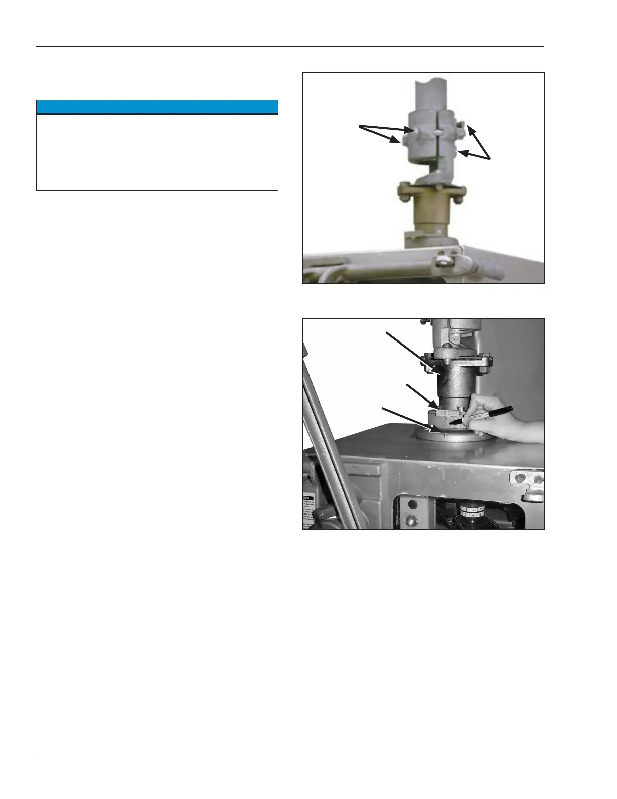
Output shaft
Position indicator
(open)
Alignment
arrow
Figure 9� Adjust the position indicator� Mark the direction
of operator rotation�