14 S&C Instruction Sheet 719-500
Installation
Using the Selector Handle (Coupling and
Decoupling)
The selector handle will be used during switch operator
adjustment. The integral external selector handle, for
operation of the built-in internal decoupling mechanism, is
located on the right-hand side of the switch operator enclo-
sure. Become familiar with the operation of the selector
handle, as described on the switch operator nameplate on
the right-hand side of the enclosure.
To decouple the switch operator from the circuit-
switcher:
STEP 1�
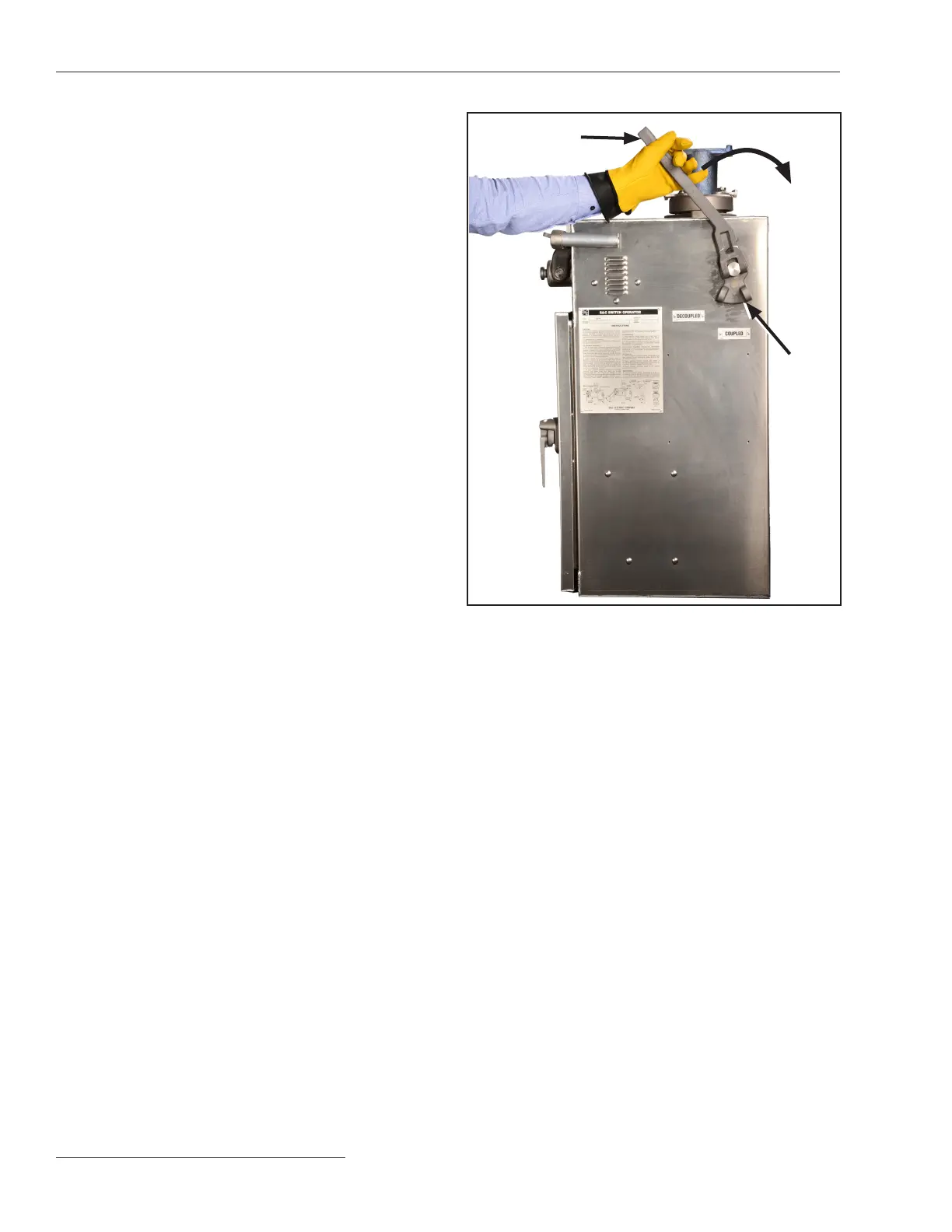
Swing the selector handle upright and slowly
rotate it clockwise 50 degrees to the Decoupled
position. See Figure 6. This decouples the switch
operator mechanism from the switch operator
output shaft.
STEP 2�
Lower the selector handle to engage the locking
tab. When thus decoupled, the switch operator
may be operated either manually or electrically
without operating the circuit-switcher.
When the selector handle is in the Decoupled
position, the shunt-trip device (when this option
is provided) is rendered inoperative.● Moreover,
in the Decoupled position, the switch opera-
tor’s output shaft is prevented from moving by
a mechanical locking device located within the
switch operator enclosure.
During the intermediate segment of the
selector handle travel, which includes the position
at which actual disengagement (or engagement)
of the internal decoupling mechanism occurs,
the motor-circuit source leads are momen-
tarily disconnected and both the “opening” and
“closing” motor contactors are mechanically
blocked in the Open position. Visual inspec-
tion, through the observation window, will verify
whether the internal decoupling mechanism is in
the Coupled or Decoupled position. See Figure 7
on page 15. The selector handle may be padlocked
in either position.
● Only the shunt-trip device is rendered inoperative� The switch opera-
tor can still be opened through the user’s protective-relay circuit� Thus
“elective” checkout of the system protective scheme is possible at
any time�
Selector handle
Locking
tabs
Figure 6� Selector handle operation (side view)�