S&C Instruction Sheet 719-500 15
Installation
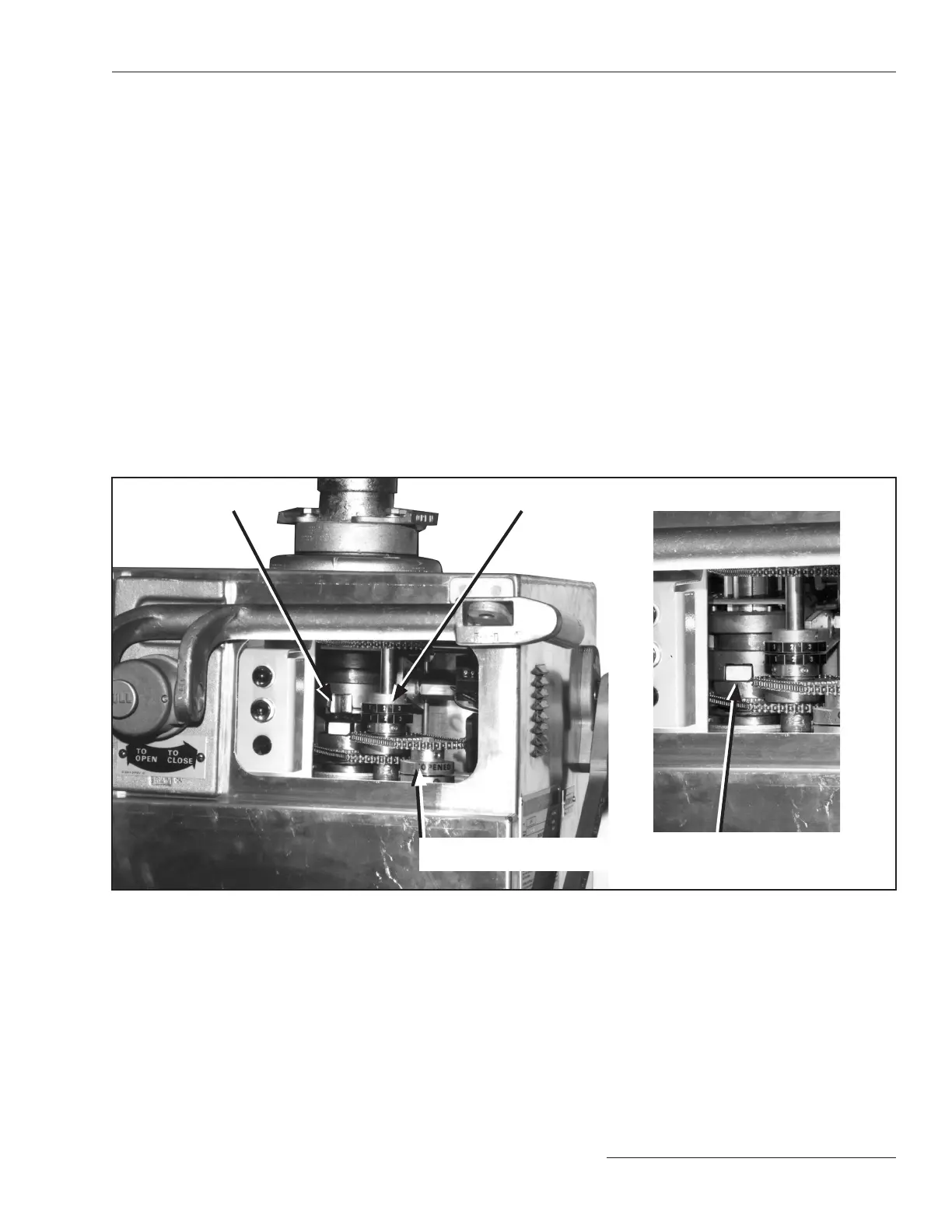
Internal decoupling mecha-
nism (coupled)
Figure 7� The internal decoupling mechanism viewed from the observation window�
Internal decoupling mecha-
nism (decoupled)
To couple the switch operator to the circuit-
switcher:
STEP 1�
Manually operate the switch operator to bring
it to the same position (Open or Closed) as the
circuit-switcher. The switch operator position
indicator, seen through the observation window,
will show when the approximate Open or Closed
position has been attained. (The position indi
-
cator for the circuit-switcher, located on the
output-shaft collar of the switch operator, will
be aligned later.)
STEP 2� Turn the manual operating handle slowly until
the position indexing drums are numerically
aligned to move the switch operator to the exact
position for coupling. See Figure 7.
STEP 3�
Swing the selector handle upright and rotate
it counterclockwise to the Coupled position.
Lower the handle to engage the locking tab. The
selector handle is now in the Coupled position.
Position indexing drums
Switch operator position
indicators