S&C Instruction Sheet 765-510 11
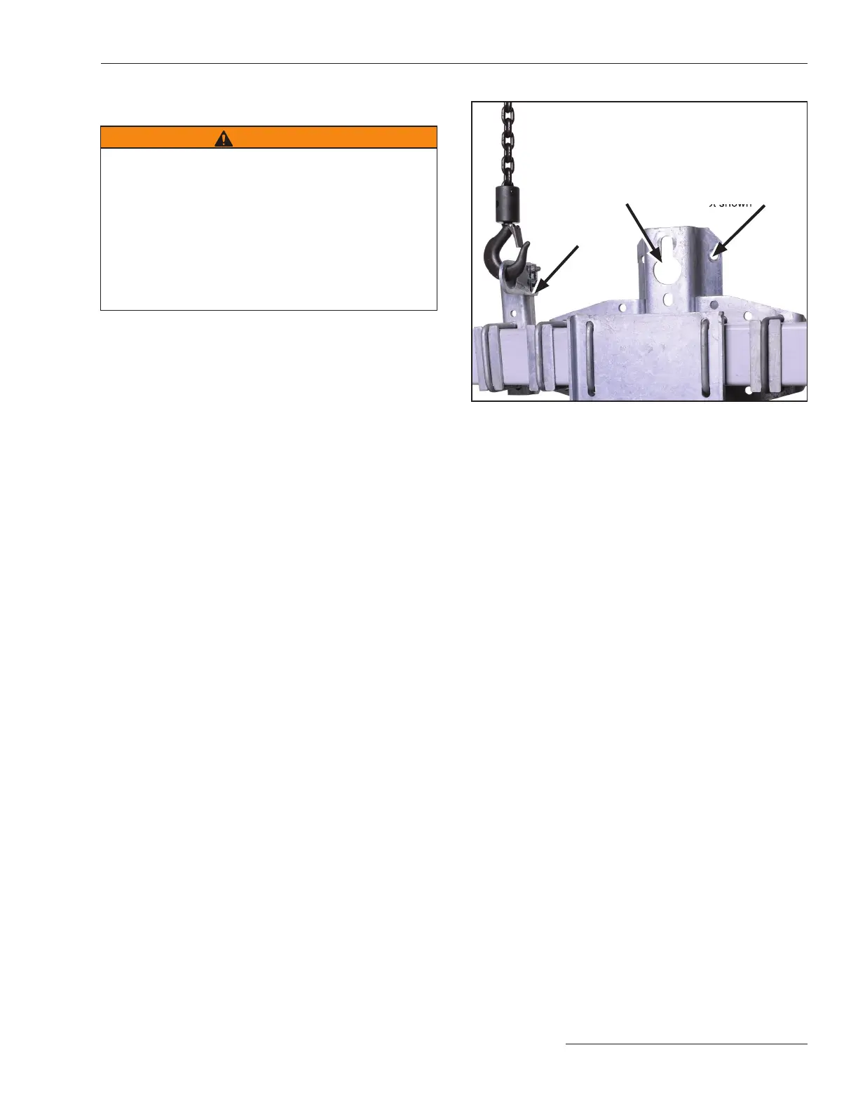
Figure 3. Hoisting the inverted mounting configuration
Omni-Rupter Switch into position.
Lifting bracket
Inverted Mounting Configuration
WARNING
Lift the switch using the lifting bracket provided. Do
not allow lifting slings to stress switch parts. Avoid
allowing the switch to swing while lifting.
Lifting the switch by the base or mounting bracket may
cause damage to the switch. Rough handling may
cause damage to the blades and contacts.
Failure to lift the switch properly can result in
switch damage, causing improper operation,
arcing, or electrical shock.
STEP 3 Switches in the inverted mounting con guration
are provided with a single-point lifting bracket
permanently attached to the switch base. See
Figure 3. To install the switch onto the pole:
(a) Make sure the switch is fully closed.
(b) Attach lifting slings ONLY to the single-
point lifting bracket.
(c) Lift the switch as shown in Figure 3 until the
lifting slings are just taut.
(d) Unbolt the switch base from the shipping
supports.
(e) Slowly and carefully lift the switch to the
proper mounting height.
(f) Guide the switch so the through-bolts
projecting from the utility pole slip into the
holes in the switch’s pole-mounting bracket.
(The pole-mounting bracket is provided with
a keyhole and an open slotted hole for ease of
installation.)
(g) Lower the switch so the pole-mounting
bracket bears down on the through-bolts.
(h) Securely tighten the through-bolts. Install
the two -inch diameter lag screws on the
front of the mounting bracket, diagonally
from each other. See Figure 3.
(i) Remove the lifting sling from the single-
point lifting bracket.
If desired, a crossarm brace (user-
furnished) may be attached to the base.
Mounting brackets for crossarm braces
must be speci ed separately. Contact your
local S&C Sales Of ce for details.
Key hole
Lag screws (2)
opposite screw
not shown
Installation

 Loading...
