S&C Instruction Sheet 765-510 13
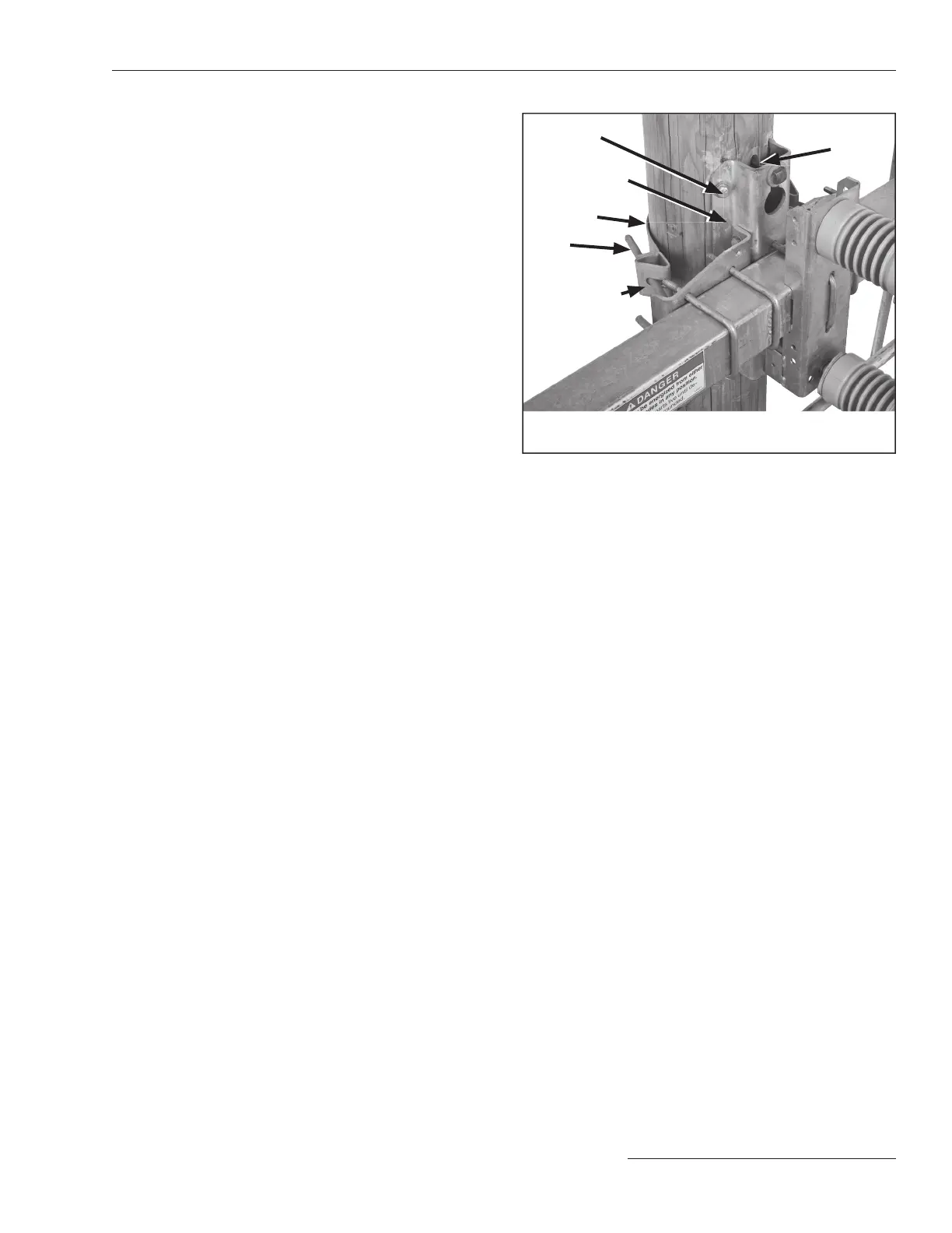
Figure 6. Typical pole-band attachment detail (vertical
mounting configuration illustrated).
● Install four lag screws on the front of the mounting bracket.
Install one lag screw to the center of the pole band.
½-inch lag
screw
●
Pole mounting
bracket
Pole band
¼ × 1 × 3 -inch
stiffening block
J-bolt
Through-bolt
Installation
Installing the Optional Pole Band
STEP 4. Secure the pole-band (optional) to the mounting
bracket on the switch, using the J-bolts provided.
See Figure 6. Two ¼ × 1 × 3-inch stiffening
blocks are furnished to be used behind the pole-
band anges and underneath the J-bolt nuts.
Fasten the pole band to the back side of the pole
through the hole in the center of the band using
one of the ve ½ -inch diameter lag screws
provided. Then, fasten the mounting bracket to
the pole using the four remaining ½ -inch lag
screws, as shown in Figure6.

 Loading...
