S&C Instruction Sheet 765-510 19
Installing the Base Covers
Base covers are only used on switches in the upright
mounting con guration. Skip to “Installing the Wildlife
Disks” section on page 20 for switches in the inverted
mounting con guration.
STEP 15. With the switch in the Closed position, place
the base covers onto the steel base of the switch
in the positions shown on the associated RD
drawing. If optional surge arrester mounting
provisions (catalog number suf x “-A1” or “-A2”)
have been speci ed for the switch, cutouts will
be provided in the base covers to t around the
arrester mounting brackets.
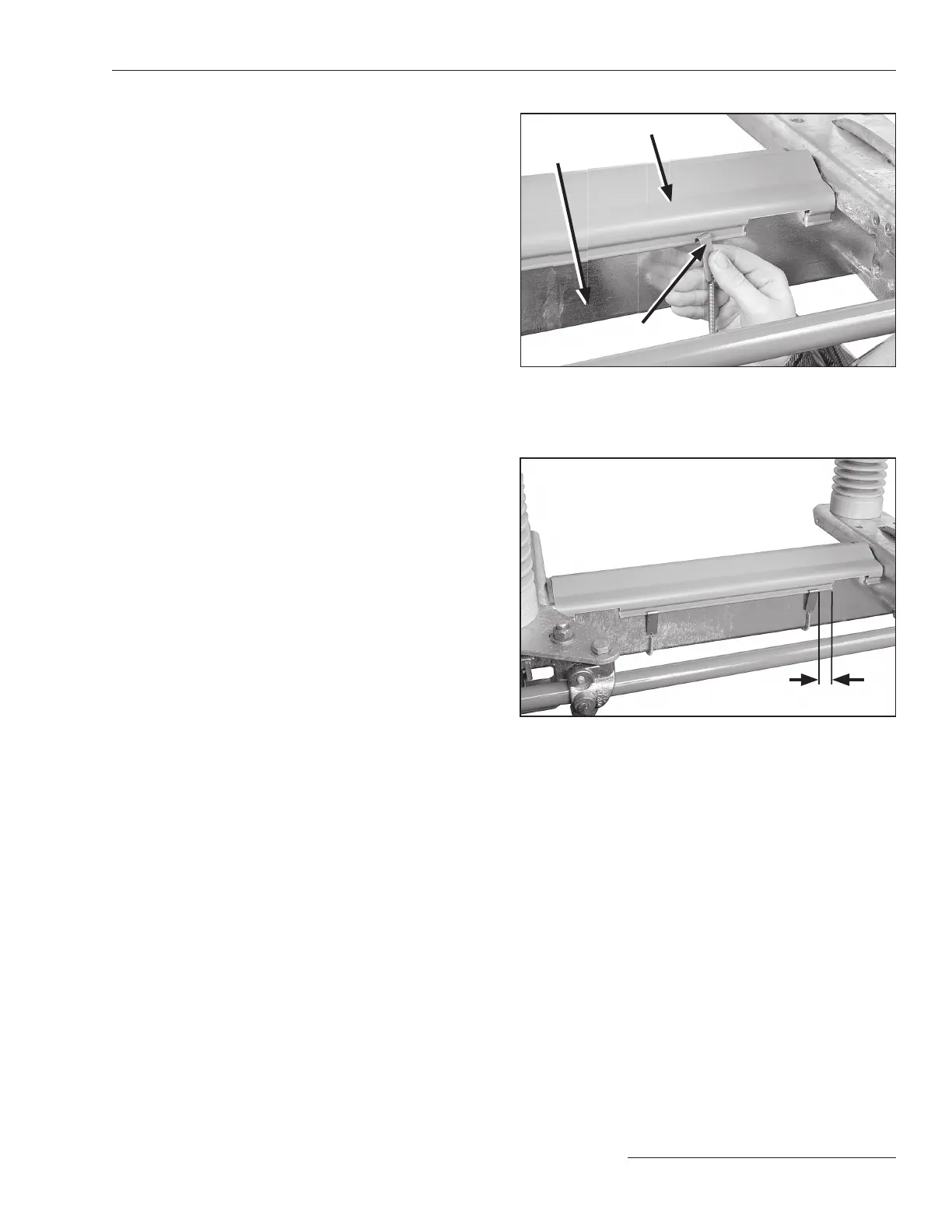
STEP 16. Hook one end of the spring clip assembly into
the lip on the edge of one side of the base cover.
See Figure 15. Bring the spring clip underneath
the switch base and stretch it until it can be
hooked into the lip on the edge of the opposite
side of the base cover. Make sure the spring clip
is approximately ½ -inch (13 mm) from the edge
of the base cover. See Figure 16. Install the
remaining spring clips on their respective base
covers in accordance with the supplied RD
drawing.
Figure 16. Make sure clips are installed approximately ½-inch
(13 mm) from the edge of the cover.
½-inch (13 mm) from edge
Figure 15. Hook one end of spring clip into the base cover
lip. Stretch underneath the base and hook the clip on the
opposite side.
Base cover
Spring clip
Switch base
Installation

 Loading...
