S&C Instruction Sheet 765-510 7
Shipping and Handling
Packing
Study the erection drawing carefully and check the bill of
materials to make sure all listed parts are at hand.
When a standard mounting arrangement is specified,
the shipment will include:
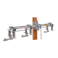
• A three-pole interrupter switch, complete with
interphase drive, factory assembled on a single base
• Four 6-feet 10-inch (208-cm) vertical operating pipe sec-
tions, predrilled, where required, for attachment to the
universal couplings
• Miscellaneous mounting hardware (less through-bolts)
for securing the Omni-Rupter Switch to the pole
• The appropriate set of operating-mechanism
components for the vertical operating pipe; e.g. handle,
guide bearings, and couplings—each tagged and keyed
to the bill of materials for ready identication
• If a standard minor modication of a standard mount-
ing arrangement is specied, the appropriate parts, as
identied in the bill of materials under sufx “-M,” “-S1,”
“-S2,” “-S6,” or “-S6L” will be included with the operating-
mechanism components. Specically, the modications
designated by these sufxes are:
-M Mounting provisions and modications for power
operation using the 6801M Automatic Switch Operator
-S1 One 2½ -inch (67-mm) diameter tubular berglass
insulating section in vertical operating shaft
-S2 One Cypoxy™ Insulator unit in vertical operating
shaft
-S6 Key interlock—single lock for “locked open”
application
-S6L Provisions only for key interlocks—mounting
bracket for interlock
“-V1,” “-V2,” or “-V3”—adds (one, two, or three respec-
tively) extra 6-foot 10-inch (208-cm) lengths of pipe and
includes the appropriate number of extra couplings and
guides
• A detailed erection drawing for the Omni-Rupter Switch
will be found in a water-resistant envelope shipped with
the switch (If a standard mounting arrangement is to
be used, this erection drawing is a printed sheet. This
same sheet is also furnished when a standard minor
modification of a standard mounting arrangement
is to be used. In the latter case, a copy of RD-7397,
“Omni-Rupter Switch Standard Minor Modications
for R4 Switches,” is included.)
Drawings for standard mounting arrangements show
only minimum or suggested locating dimensions for the
vertical-operating-pipe guide bearings and the operating-
handle assembly. Specific locations are to be determined
either on the job or by the user’s engineering department.
Inspection
Examine the shipment for external evidence of damage as
soon after receipt as possible, preferably before removal
from the carrier’s conveyance. Check the bill of lading to
make sure all listed shipping skids, crates, and containers
are present:
If there is visible loss and/or damage:
1. Notify the delivering carrier immediately.
2. Ask for a carrier inspection.
3. Note the condition of shipment on all copies of the
delivery receipt.
4. File a claim with the carrier.
If concealed damage is discovered:
1. Notify the delivering carrier within 15 days of receipt
of shipment.
2. Ask for a carrier inspection.
3. File a claim with the carrier.
Also, notify S&C Electric Company in all instances of
loss and/or damage.

 Loading...