12 S&C Instruction Sheet 662-510
Switching with Mini-Rupter
®
Switches
Operating the Mini-Rupter Switch
The Mini-Rupter Switch is a three-pole, 600-A switch used
to switch between power sources. The operating shaft
used to control the switch is located on the same side of
the enclosure with respect to the switch location.
Before proceeding with the instructions on operating
the Mini-Rupter Switch, refer to the “DANGER” message
on page 7.
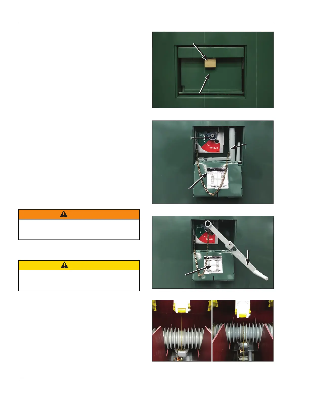
STEP 1. Remove the padlock and open the switch-
operating-shaft access cover. See Figures 10(a),
10(b), and 10(c).
STEP 2. Remove the folding switch-operating handle
from its storage pocket behind the access cover.
Unfold the handle until it is latched and slide it
onto the hex switch-operating shaft.
Note the switch-position indicator that is
attached to the hex switch-operating shaft
and rests against a stop in either the Open or
Closed position.
STEP 3. Rotate the handle in the appropriate direction
to open or close the switch, and check the
switch-position indi cator to verify the switch is
in the desired position.
STEP 4. Follow the instructions to open the enclosure
doors on page 10.
STEP 5. Check the physical position of the switch
by using the viewing window provided
in the switch-termination compartment. See
Figure 11.
WARNING
Always confirm the Open/Close position of the Mini-
Rupter Switch by visually observing the position of
the switch blades.
STEP 6. Remove and fold the switch-operating handle,
and return the handle to its storage position.
Then, close and padlock the access cover.
CAUTION
Do not leave the switch-operating-shaft access cover
unlocked if the gear is left unattended by qualified
persons.
Folding
switch-
operating
handle in
operating
position
Folding
switch-
operating
handle in
storage
pocket
Access
cover
opened
Figure 10(a). The access cover padlock.
Hood shields padlock
shackle
Access cover in
padlocked position
Hex
switch-
operating
shaft
Figure 10(b). The access cover door is open.
Connection
diagram
(a)
(b)
Figure 11. (a) Shows the switch in the Closed position, and
(b) shows the switch in the Open position.
Figure 10(c). The switch operating handle installed.