22 S&C Instruction Sheet 662-510
Switching with Uni-Rupter
®
Interrupters
DANGER
Make sure the fuse is kept away from the
con tacts of the Uni-Rupter Interrupter
during removal of the fuse from its hinge to
prevent reestablishment of the cir cuit.
S&C recommends the associated dual-
purpose front barrier be placed in the
“Slide-in” position whenever a fuse is
open or is being removed from or installed
into its hinge.
STEP 8. For 25-kV Fault Fiter Electronic Power
Fuses: De-energize, test, and properly ground
the mounting in accordance with local operating
practices, and then remove the fuse from its
mounting by hand using suit able personal
protective equipment (PPE).
STEP 9. Hang the dual-purpose front barrier in its
normal, sus pended position using the Grappler
tool. See Figure 17 on page16. Also install the
optional inner barrier panel, if furnished. Then,
close and latch the doors, and padlock securely.
Pull on the doors to verify they are securely
latched.
WARNING
If fuses are removed from the mountings,
they should be stored in a clean, dry
location. Do not store end-fit tings,
holders, interrupting modules, or current-
limit ing fuses in high-voltage compartments
unless the unit is equipped with the
optional fuse-storage feature (cat alog
number suffix “-E1,” “-E2,” or “-E3”)
suitable for this purpose.
The optional Fuse Storage feature, if fur-
nished, can accommodate three completely
assembled spare Type SML Fuses, two spare
Fault Fiter Interrupting Modules, one spare
Fault Fiter Electronic Power Fuse Holder, or
one spare current-limiting fuse holder in each
switch com partment, as applicable. The Fuse
Storage feature is mounted inside the enclo-
sure, between the interrupter switch and the
side wall of the enclosure. For storage, position
the assembled fuses in the Fuse Storage fea-
ture as shown on the label headed “STORAGE
AND HANDLING OF SPARE FUSES” affixed to
the inside of each applicable switch-compart-
ment door.
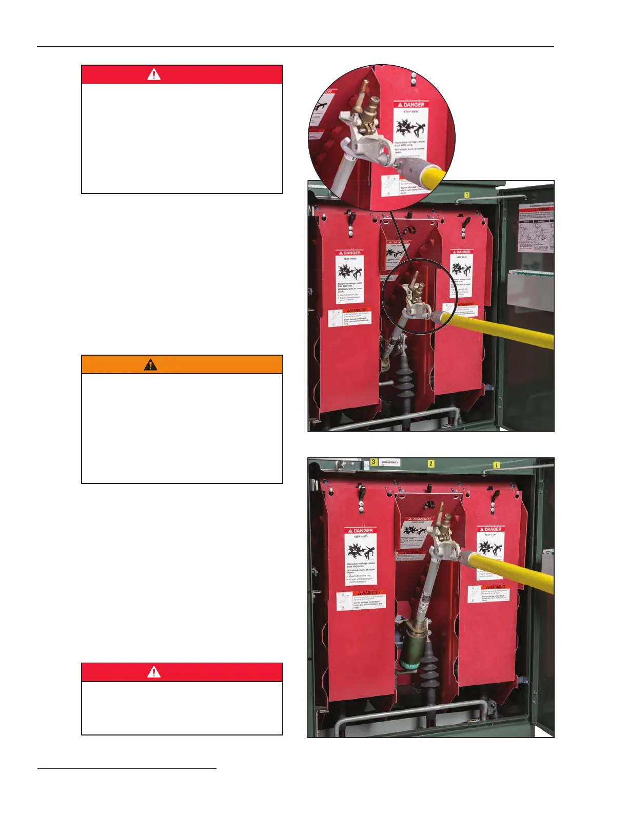
DANGER
Do not handle spare fuses unless the
front barriers for the switches are in their
normal, suspended positions to guard
against inadvertent contact with live parts.
Figure 27. Removing a fuse from its hinge with a forward and
upward lifting motion.
Figure 26. A Grappler tool positioned for fuse removal.