Home
Sandel
GPS
sn3500 ehsi
Page 28 (Figure 7-13 between Layers)
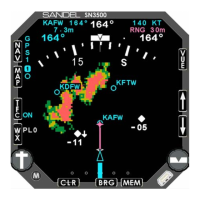
Sandel sn3500 ehsi - Figure 7-13 between Layers
42 pages
Manual
Save Page as PDF
To Next Page
To Next Page
To Previous Page
To Previous Page
Loading...
WEATHER DISPLAY INTERFACE
82005-PG-D
SANDEL SN3500 EHSI PILOT’S GUIDE
PAGE
7-11
Figure 7-13 Between layers
WEATHER DISPLAY INTERFACE
82005-PG-D
SANDEL SN3500 EHSI PILOT’S GUIDE
PAGE
7-12
(This page intentionally left blank)
27
29
Table of Contents
Main Page
Default Chapter
1
Navigation Display
1
Copyright
2
Revision Notice
2
Operational and Legal Issues
2
Approvals
2
Conventions Used in this Manual
2
Table of Contents
3
Table of Figures
4
Chapter 1 Welcome to the Sn3500 Ehsi
6
What Is the SN3500
6
Chapter 2 Display Overview
7
SN3500 Physical Features
7
Display Areas
7
Indicators
7
Figure 2-1 SN3500 Physical Features
7
Figure 2-2 Display Areas
7
Data Color Coding
9
Chapter 3 Basic Operation
10
Overview
10
Power-Up Displays
10
Selecting the Data
10
Figure 3-1 Introduction Screen
10
Figure 3-2 SN3500 Display with Compass Card
10
Selecting the Primary NAV Source
11
Selecting and Displaying Bearing Pointers 1 & 2
11
Displaying the Map Data
11
Figure 3-3 NAV Source Annunciations
11
360-Degree FULL View and 70-Degree ARC View
12
Auto-Slewing the Course Pointer
12
Heading Bug Sync
12
Course Pointer Sync
12
Transitioning from GPS/FMS to ILS
12
MEM Function
12
Figure 3-4 Full View Figure 3-5 Arc View
12
Display and Button Brightness
13
Figure 3-6 Brightness Menu
13
Chapter 4 Nav Operation
14
GPS Mode Selection
14
Auto-Slew Function
14
Course Pointer Display Function
14
Figure 4-1 NAV Menu
14
Figure 4-2 Auto-Slew Setup Menu
14
Figure 4-3 Course Pointer Setup Menu
14
Chapter 5 Bearing Pointers
16
Bearing Pointers
16
BRG Menu
16
Chapter 6 Map Operations
17
Overview
17
Internal Database
17
Map Controls and Displays
17
Map Memories
18
Map Database Items
18
Figure 6-1 Map Operation
18
Getting Started - Example
19
Map Setup
19
Map Memory Settings
20
Figure 6-2 Map Setup Menu
20
Figure 6-3 Select "AIRSPC
20
Figure 6-4 Select "ON
20
Storing Settings into Preset Memories
21
Removing a Map Memory from the Rotation Sequence
21
Restoring Default Settings
21
Figure 6-5 Storing Settings
21
Figure 6-6 Removing Map Memory
21
Copying Map Settings into the Scratchpad
22
Automatic Decluttering
22
Maximum Range of Internal Map Data
22
Clearing the Map Display
22
Figure 6-7 Restoring Default Settings
22
Figure 6-8 Copying Map Settings
22
Chapter 7 Weather Display Interface
23
WX-500 Stormscope® Data
23
WX Menu
23
Figure 7-1 WX-500 Stormscope Display
23
Figure 7-2 WX Setup Menu
23
Figure 7-3 Display Menu
23
FIS-B Datalink Weather
24
General Operation
24
Figure 7-4 WX-500 Mode Menu
24
Figure 7-5 LTNG SRC Mode Menu
24
Figure 7-6 FIS-B Weather Display
24
Precipitation Intensity
25
FIS-B Lightning
25
FIS-B Services Backgrounder
25
Figure 7-7 Precipitation
25
Figure 7-8 FIS-B Lightning Strike Age
25
Examples
26
Figure 7-9 FIS-B Information Flow
26
Figure 7-10 Precipitation Example
27
Figure 7-11 Visible Moisture Observed
27
Figure 7-12 no Visible Moisture Observed
27
Figure 7-13 between Layers
28
Chapter 8 Traffic Display Interface
29
Traffic Symbology
29
Relative Altitude
29
Traffic Display Mode
29
Altitude Mode
29
Figure 8-1 SN3500 with Traffic
29
Traffic Overlay with Moving Map
30
TFC Menu
31
Figure 8-2 Traffic with Moving Map
31
Figure 8-3 on AUTO Menu
31
Figure 8-4 Altitude Range Menu
31
Figure 8-5 Altitude as Flight Level Menu
31
Chapter 9 Flags and Abnormal Conditions
32
Chapter 10 Messages
34
Figure 10-1 Message and "ACK" Button
34
Chapter 11 Technical Specs and Operating
38
Chapter 12 Installation Information
39
Chapter 13 Glossary
40
Chapter 14 Avionics Acronyms
41