TR90-Series Due to continuing product development, specications are subject to change without notice. © 2018 S&P
132104_002 Revised 9/2018 Page 4
Installing Outside Air & Exhaust Air Ducts
Ducts connecting the unit to the outside must be well- insulated.
Vapor barrier is required on both inside and outside of the insulation.
Band or tape inner duct liner to inner ange of appropriate collar.
Drive a sheet metal screw through liner to secure duct spiral wire
to collar. Straighten insulation, and slide outer duct jacket onto
the outer ange of the duct collar. Secure with band or tape.
The vapor barrier should be continuous and sealed against air
and moisture leakage! If not, condensation or ice may form
in cold weather on the duct surface or in its insulation!
The inlets and outlets should be screened against insects and vermin
and shielded from the weather to prevent the entry of rain or snow.
INSTALL FRESH AIR INLET AWAY FROM SOURCES OF CONTAMINANTS.
• Do not locate the fresh air inlet where vehicles may be
serviced or left idling.
• The fresh air inlet should be at least ten feet away from
any exhaust such as dryer vents, chimneys, furnace, and
water heater exhausts or other sources of contamination
or carbon monoxide.
• Never locate the fresh air inlet inside a structure.
Installing Return Air (RA) Ducts
All the stale air returns are connected by ducts to the unit.
Generally, empty stud cavities are used for returns as is often
done with cold air returns for the furnace, using standard duct
boots to connect to six inch pipe at the bottom or top of the
wall cavity. Always be sure to seal all joints with duct sealant
or tape. Some local codes may require metal ducting all the way
from the boots to the stale air grilles. Use rigid ducts to allow the
air to move freely and easily through the ducts. See chart under
System Layout to size your ductwork:
If duct runs are very long (over 30 feet of ex duct for 90 CFM) or
have excessive bends or elbows or if maximum air ow rates are
required, eight inch insulated exible duct should be used. The
outer ange of the duct collar can be used for both the inner and
outer jacket of the exible duct. Care must be taken to insure
that the duct is securely fastened and sealed to the duct collar.
Do not use more ex duct than necessary!
Flex duct is much more resistant to airow than rigid duct; longer
runs of ex duct will reduce the ventilation performance of your
system. Stretch ex duct and avoid sharp bends.
• Do not connect Dryers directly to the unit.
• Do not connect Range Hoods to the unit.
NOTE: Seal all duct collars at unit to minimize air leakage.
Electrical Connections
NOTE: DISCONNECTION MEANS. Most electrical codes require
that the unit be disconnected for service. Depending on local
codes, an electrical outlet (for TR90) or an on/o switch
available for the unit (TR90G) may satisfy this requirement.
Power supply connection to TR90G is made in its electrical box
through the hole in the end pan. Pull out the unit electrical box
and connect the power wire conductors to the terminal block
inside the electrical box. The terminal block inside the electrical
box is conveniently marked for connection of eld power wiring.
After connecting the power wire conductors to the terminal
block re-install the electrical box in the unit.
S&P oers the TR90 with a line cord for connection to an
electrical outlet. If a TR90 with a line cord is installed and the
installer desires to convert to eld power wiring, should local
codes permit, simply remove the line cord from the terminal
block and connect eld wiring as described above.
Installing Controls
The TR90 is oered with a control board for connection to external
controls. The TR90G runs continuously whenever power is supplied to it.
Optional Controls:
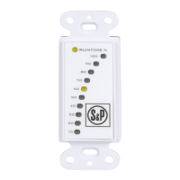
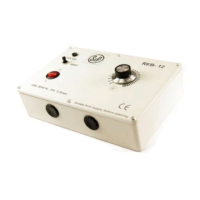
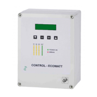
S&P oers a variety of controls specically designed to work with
the TR90. These include: SPTL (a two wire proportional timer),
SFM (a six wire proportional timer that interconnects to the
furnace blower), and SPBL (point of use push button control).
Other controls that throw an unpowered switch may also be
used. The TR90G is a line voltage unit that may be controlled
with any line voltage control switch.
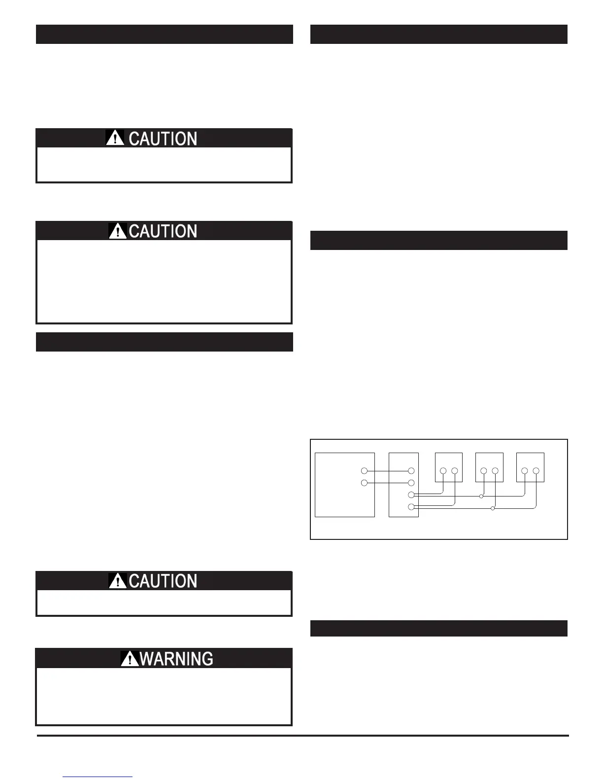
Typical Control Schematic:
Various wiring designs can be used to properly control the unit
and meet safety and code concerns. Consult your electrician for
an electrical design to meet your needs. The schematic below
shows a typical control system: a SPTL proportional timer plus
two SPBL push-button controls.
See installation manuals for the control(s) you select for wiring
diagrams and specic instructions.
If NOT connecting controls to the TR90:
Make a jumper out of a short piece of wire. Connect the jumper
wire to the screw connections of the terminal strip on the outside
of the unit. ERV runs full-time once its power cord is plugged in.
Starting Up the Unit
• Inspect your installation to be sure all duct work is correctly
installed and sealed, that lters are in place, and controls
(if any) are connected.
• Shut and latch the door to the unit.
• Provide 120 VAC power to the unit. It may start immediately.
• Use control, if any, to turn on the unit. Check operation of
the control(s).
• Check that the unit’s safety interlock switch turns o the
unit when the door is opened.
Up to (6) SPBL Controls, wired in parallel, may be used.
TR
SPTL
SPBL
1
Only (2) SPBL Controls can be directly connected to the SPTL Control.
Wire any additional SPBLs in parallel with the first two.
R
C
PB
PB
SPBL
2
SPBL
3
* TR90 only.
(Not TR90G)
DANGER OF ELECTRICAL SHOCK WHEN SERVICING AN
INSTALLED UNIT.
ALWAYS UNPLUG UNIT BEFORE CONNECTING OR
SERVICING CONTROLS.
 Loading...