SEC1000 FIRE ALARM CONTROL PANEL
3.7 Maximum loop cable length recommendations
To ensure a reliable system, some care must be taken when calculating the appropriate cable
gauge for the system. The main limitation is that during an alarm condition (maximum current
draw), the maximum volt drop at the end of the loop must be at least 19 Volts . The exact
calculation equations are beyond the scope of this manual, because of the distributed load of
the sounders on the loop. The following table gives a rough guide for maximum cable lengths
at various current loads for 3 different cable gauges.
MAXIMUM LOOP CURRENT(IN ALARM)
Cable Resistance
3.8 Other terminal connections
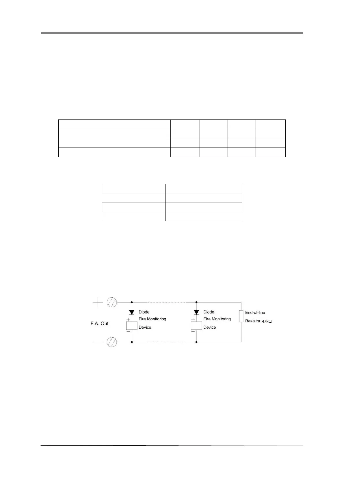
1. F.A. Out short for Fire Alarm Output: When there is a general fire the output is activated. A
47K end-of-line resistor (provided) is connected at the end of the circuit to allow the wiring to
be monitored. If the circuit is unused, the 47K resistor must still be connected. It is also
monitored for open or short circuit fault of its wiring. A typical connection is shown below.
2. Fault Out short for Fault Output: The NO and COM are closed in normal state. When there
is a general fault, this voltage free relay switches.
3. S.C. Out short for Sounder Circuit Output: A conventional sounder circuit is provided.
When there is a general fire it activates the sounders connected by default. The sounders can
be aborted and restarted by pressing the SILENCE button. It can be disabled, therefore no
output under disabled state. It is also monitored for open or short circuit fault of its wiring. A
typical connection is shown below.
 Loading...