EasyManua.ls Logo

Sansui MC-X7 User Manual

Sansui MC-X7
12 pages
To Next Page IconTo Next Page
Page #1 background imageLoading...
Page #1 background image
SERVICE
MANUAL
6I
SANSUI!
MI
>,
4
}
|
BI
SANSUI
MINI
COMPONENT
SYSTEM
<COMPACT
DISC
PLAYER
SECTION>
Organization
of
System
Component
Amplifier
Tuner
CD
Player
Cassette
Deck
|
Optional
Speaker
SET
NAME
A-X7
T-X7,
T-X7L
CD-X7
S-X7
Note:
Set
name
is
shown
on
the
rear
panel.
CAUTION
1.
Parts
identified
by
the
A,
symbol
on
the
schematic
diagram
and
the
parts
list
are
critical
for
safety.
Use
only
replacement
parts
that
have
critical
characteristics
recommended
by
the
manufacturer.
.
Make
leakage-current
or
resistance
measurements
to
determine
that
exposed
parts
are
acceptably
insulated
from
the
supply
circuit
before
returning
the
appliance
to
the
customer.
¢
Specifications
;
:
UL
Manufactured
for
U.S.A.
market.
FOP
At
cicero
dees
Compact
disc,
digital
audio
system
pts
Stencerd
Version
?
(UL
and
XX
mode!
only)
°
,
anuiaciur
or
Canadian
m
PICKUP........c.ccceercsossersserresearononeocoees
3-Beam,
semiconductor
laser
fy
Pectectured
to:
Eaesaan
aree
PRODUCT
COMPLIES
WITK
DHHS
Decoding
(D/A).............cseseccceseseees
1-Bit
/
MASH
RULES
21
CFR,
SUBCHAPTIR
J,
(MASH
is
trademark
of
NTT)
MANUFACTURED:
Frequency
response..................0
4
Hz
to
20
kHz,
+0.5
dB
Total
harmonic
distortion...
..........
Less
than
0.006%
(1
kHz)
(CSA
model
only)
Signal-to-Noise
ratio...
.............--.
Better
than
103
dB
CERTIFIELD
ONLY
TO
CANDIAN
Dynamic
range........
.....scscccreeereree
Better
than
99
dB
ELECTRICAL
CODE.
A
hide
&
Flutter...
.eecsseseseeeeeeeneeees
ite
direc
aan
limit
CANADIAN
DEL
ELECTAICTE
ITTENSIONS............ccceeceeceeeeeserseeeees
mm
(8-
84
mm
(3-5/16")
H
280
mm
(1
1-1/1
6°)
D
(EU
model
only)
WEIGHNT...........-.ccsccrsssseecessseeeeesce
ness
2.0
kg
(4.41
Ibs)
net
*
Design
and
specifications
subject
to
changes
without
notice
for
cence
improvements.
LASER
PRODUIT
a
LARD
CONT
SSAA
OTT
Ol
CAUTION:
USE
OF
CONTROLS
FOR
ADJUSTMENTS
OR
PERFORMANCE
OF
PROCEDURES
OTHER
THAN
THOSE.
des
ech
{EU
model
only)
*
The
following
label
has
been
affixed
to
the
unit,
listing
the
proper
procedure
for
working
with
the
laser
beam.
.
ADUARSELI
1.
THIS
LABEL
IS
ATTACHED
TO
THE
PLACE
AS
ILLUSTRATED
TO
uiquiug
LasensTalieis
yen
eee
INFORM
THAT
THE
APPARATUS
CONTAINS
A
LASER
COMPO-
AF
FUNKTION.
UNOGA
LOS
ATTELSE
NENT.
2.
THIS
LABEL
IS
ATTACHED
TO
THE
INSIDE
OF
THE
TOP
COVER
AS
ILLUSTRATED,
SO
THAT
ANY
FURTHER
PROCEDURE
WILL
Soe
THE
USER
INTO
EXPOSURE
WITH
THE
LASER
BEAM.
.
3.
THE
WARNING
LABEL
INFORMING
OF
RADIATION
IS
PLACED
INSIDE
THE
UNIT.
AS
SHOWN
IN
THE
ILLUSTRATION,
TO
WARN
AGAINST
FURTHER
MEASURES
ON
THE
UNIT.
THE
EQUIPMENT
CONTAINS
A
LASER
COMPONENT
RADIATING
LA-
SER
RAYS
EXCEEDING
THE
LIMIT
OF
LASER
PRODUCTS
OF
CLASS
1.
Question and Answer IconNeed help?

Do you have a question about the Sansui MC-X7 and is the answer not in the manual?

Sansui MC-X7 Specifications

General IconGeneral
BrandSansui
ModelMC-X7
CategoryStereo System
LanguageEnglish

Summary

Product Overview and Safety Cautions

System Components Organization

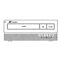
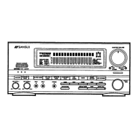
Lists the main components of the MC-X7/X7L system.

General Safety Precautions

Critical safety notes on parts, insulation, and leakage current measurements.

Laser Safety Precautions

Warnings and procedures for handling laser components, Class 1 laser product.

Block Diagram

CD Player Block Diagram

Illustrates the functional blocks of the CD player section.

Component Replacement Procedures

Bonnet Removal Procedure

Step-by-step guide for removing the unit's bonnet.

Tray Panel Removal Procedure

Instructions for safely removing the CD tray panel.

Front Panel Removal Procedure

Steps to remove the front panel of the unit.

Mechanism Assembly Replacement

Guidance on replacing the CD mechanism assembly.

CD Mechanism Exploded View

CD Mechanism Exploded View and Parts List

Detailed exploded diagram of the CD mechanism with parts list.

System Control Socket Pinouts

15-Pin System Control Socket Pinout

Pinout details for the 15-pin system control socket.

17-Pin System Control Socket Pinout

Pinout details for the 17-pin system control socket.

Mechanism Assembly Part Numbers

Lists part numbers for mechanism assemblies.

Parts List by Board

F-6557 Main Board Parts List

Lists components for the F-6557 main board.

F-6558 Control Switch Board Parts List

Lists components for the F-6558 control switch board.

F-6559 Power Indicator Board Parts List

Lists components for the F-6559 power indicator board.

Adjustment Procedures

Tracking Offset Adjustment

Procedure for adjusting tracking offset using fVR1.

Focus Offset Adjustment

Procedure for adjusting focus offset using fVR2.

Tracking Gain Adjustment

Procedure for adjusting tracking gain using fVR3 and fVR4.

Adjustment Location Diagram

Diagram showing specific adjustment points (TP1, TP2, fVR1-fVR4).

Component Location on Boards

F-6557 Main Board Component Layout

Shows physical locations of components on the F-6557 main board.

F-6558 Control Switch Board Layout

Shows component locations on the F-6558 control switch board.

F-6559 Power Indicator Board Layout

Shows component locations on the F-6559 power indicator board.

Other Parts Identification

Lists and identifies various external parts of the unit.

Schematic Diagrams

RF Servo Schematic Diagram

Detailed schematic for the RF servo section.

Logic Control Schematic Diagram

Detailed schematic for the logic control section.

Power Supply Schematic Diagram

Detailed schematic for the power supply section.

Digital/Analog Schematic Diagram

Detailed schematic for the digital and analog sections.

IC Functions and Block Diagrams

CXA1081S (RF Amp.) Function and Diagram

Block diagram and pin functions for the CXA1081S IC.

CXA1372Q (Focus/Tracking Servo) Function and Diagram

Block diagram and pin functions for the CXA1372Q IC.

IC Functions and Block Diagrams (Continued)

TC4053BP (Multiplexer) Function Details

Details the truth table and functions of the TC4053BP IC.

CXD2500Q (Digital Signal Processing) Function Details

Details pin functions and internal blocks of the CXD2500Q IC.

Packing and Accessory List

Packing List Details

Lists the items included in the product's packaging.

Accessory List Details

Lists included accessories such as remote control and antennas.

Related product manuals