13
HERE WE GO!
Sc
an h
e
r
e
to
vi
ew
you
r in
st
a
ll vid
eo.
M
odel
:
SLF8-B1
6700-004620
<00>
Locate
yo
ur studs and
choose a
h
eight
f
or your
T
V, th
en
simply tap
e this temp
late to
the w
all,
and
y
ou can dr
i
ll right th
r
o
ugh.
san.u
s/
9
6
9
san.u
s/
9
7
1
T
H
I
S IS YOUR DRILLING TEMPLATE
FOR S
T
EP
2
WELCOME AND THANKS FOR CHOOSING SANUS SIMPLICITY
YOU’RE REALLY GOING
TO E
NJOY STEP 3
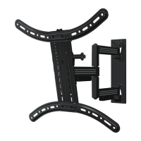
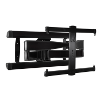
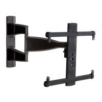
Onc
e
t
he wal
l
pla
te is installed
,
attac
h the a
r
m
t
o th
e
wall plate
. N
ext, simply pic
k
-up
y
o
ur T
V
, hang
i
t
on the
a
rm,
and sec
u
r
e it. C
ong
r
a
tulations!
Y
ou’re
done.
We'
re here to
help
!
If you h
a
ve
q
ue
s
tio
ns
a
t
an
y
po
int, co
nt
act
c
u
st
o
mer
serv
ice
at:
1-888-3
33-137
6
M
o
n
day
–
F
rid
ay
8
A
M
–
9
PM
CST
Sa
t
u
rday – Sun
d
ay
1
0
:3
0
A
M
–
7
PM
CST
Fro
m y
o
ur typical vi
ewing location, position you
r
T
V so
your eyes ar
e
l
ev
e
l with th
e midd
le of the
sc
reen. For most
peo
ple, this is
b
etween
4
0
"
and 60 " (101 cm and 152 cm)
ab
ove the floo
r. For pre
cise drilli
n
g locati
o
ns,
sca
n the
He
i
ghtWi
zard
™
link be
l
o
w or
c
ontac
t custome
r
service.
GET
S
TARTED
WITH STEP 1
VIEWING HEIGHT
R
E
COMMENDATION
Grab t
he TV
brac
k
e
ts and line t
hem up
with the h
oles on the bac
k
o
f your T
V.
Att
ach using the
b
olts that
fi
t.
Refer
ence the
p
r
od
u
c
t
m
a
nual
for
detail
s on m
oun
ting to
con
crete.
B
e
sur
e to
r
evi
ew
t
he manu
a
l
for
comp
lete
sa
fety
i
ns
tructions.
40
–
60
in.
101 – 152 cm
10°
1
0
°
THIS
W
A
Y
UP
3 4
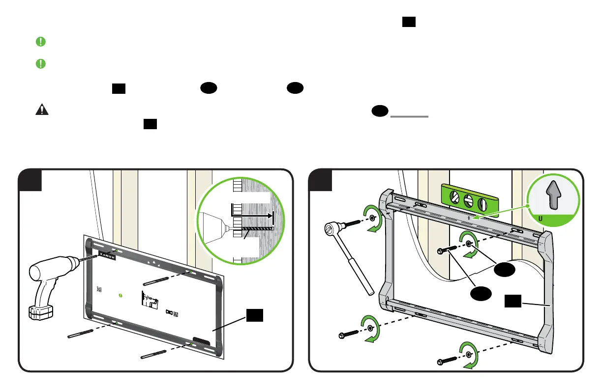
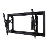
3. Drill pilot holes using a 7/32 in. (5.5 mm) diameter drill bit, then remove the wall plate template
19
.
IMPORTANT: Be sure to drill into the center of the stud.
IMPORTANT: Pilot holes must be drilled to a depth of 3 1/2 in. (89 mm).
4. Install the wall plate
20
using four lag bolts
21
and four washers
22
. Tighten all lag bolts only until they are pulled firmly against the wall plate.
CAUTION: Avoid potential personal injury or property damage! All four lag bolts
21
MUST BE firmly tightened to prevent unwanted
movement of the wall plate
20
.
Ensure the wall plate is securely fastened to the wall before continuing on to the next step.
Go to STEP 3 on PAGE 16.
20
19
3½ in. (89 mm)
7/32 in.
(5.5 mm)
21
22
UP ARROW