16
STEP 3 Attach TV to Wall Plate
HERE WE GO!
Scan her e to view
your install video.
Model: SLF8-B1
670
0-004620 <00>
Locate your studs and choose a height for your
TV, then simply tape this template to the wall,
and you can drill right through.
san.u
s/969
san.us/971
THIS IS YOUR DRILLING TEMPLATE
FOR STEP 2
WELCOME AND THANKS FOR CHOOSING SANUS SIMPLICITY
YOU’RE REALL
Y GOING
TO ENJOY STEP 3
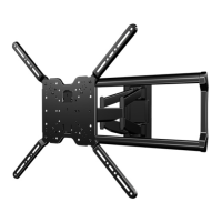
Once the wall plate is installed, attach the arm to the
wall plate. Next, simply pick-up your TV, hang it on the
arm, and secu
re it. Congratulations! You’r
e done.
We're here to help!
If you have questions at any point, contact customer service at:
1-888-333-1376
Monday – Friday 8
AM
– 9
PM
CST
Saturday – Sunday 10:30
AM
– 7
PM
CST
From your typical viewing location, position your TV so
your eyes are level with the middle of the screen. For most
people, this is between 40 " and 60 " (101 cm and 152 cm)
above the floor. For precise drilling locations, scan the
Heigh
tWizard
™
link below or contact customer service.
GET STARTED
WITH STEP 1
VIEWING HEIGHT
RECOMMENDATION
Grab the TV brackets and line them up
with the holes on the back of your TV.
Attach using the bolts that fit.
Reference the product manual for
details on mounting to concrete.
Be sure to review the manual for
complete safety instructions.
40 – 60 i
n.
101 – 152 cm
10°
10°
THIS WAY UP
5/16 x 3 1/2 in.
M4
M6/M8
22mm
M8 X 12 mm
.890 x .375 x .077 in.
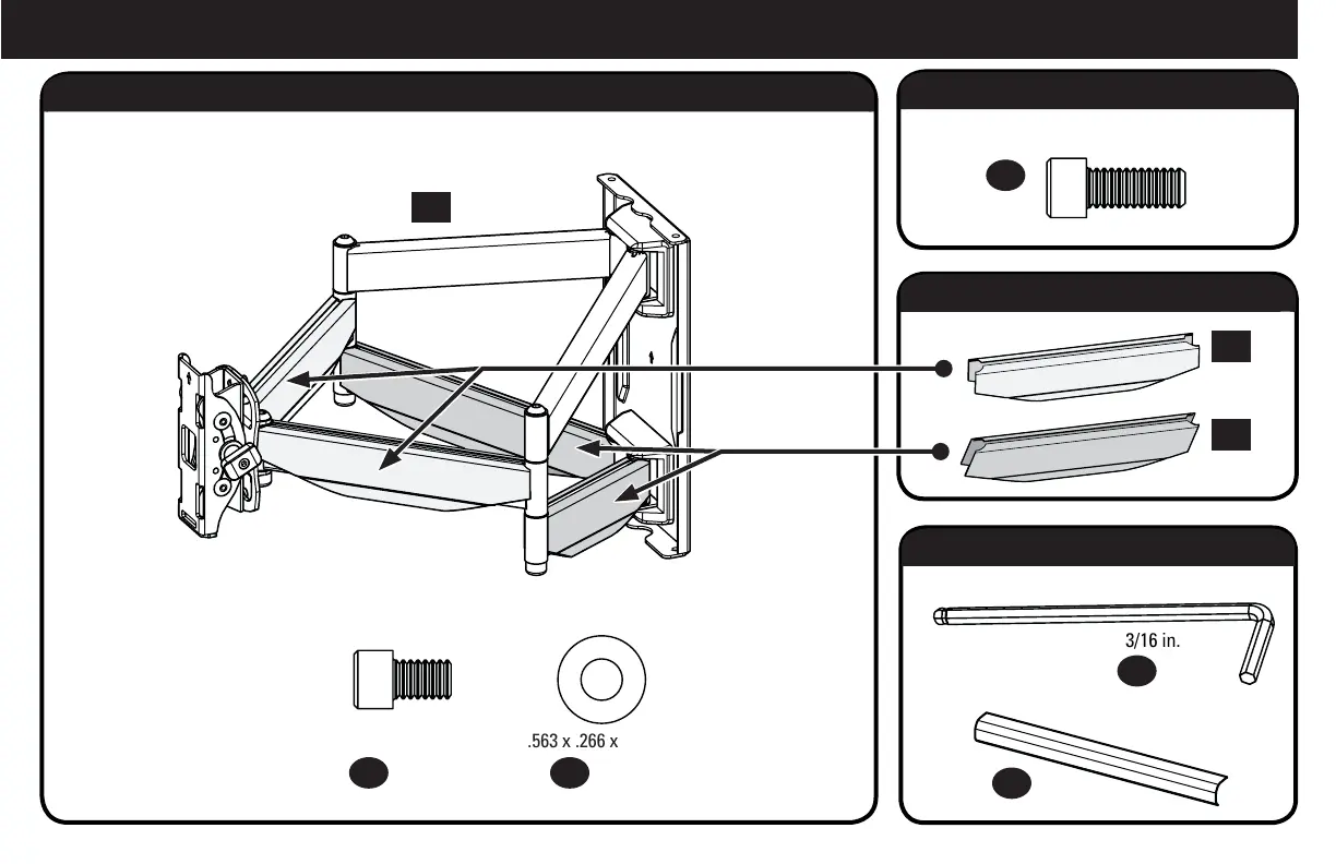
.563 x .266 x .050 in.
1/4-20 x 3/8 in.
1/4-20 x 5/8 in.
M4 x 12mm
M6 x 12mm
M6 x 35mm
M4 x 35mm
M6 x 20mm
M8 x 16mm
M8 x 35mm
M8 x 25mm
M8 x 20mm
3/16 in.
2.5mm
M8 x 45mm
M8 x 50mm
HERE WE GO!
Scan he re to view
your install video.
Model: SLF8-B1
670
0-004620 <00>
Locate your studs and choose a height for your
TV, then simply tape this template to the wall,
and you can drill right through.
san.u
s/969
san.us/971
THIS IS YOUR DRILLING TEMPLATE
FOR STEP 2
WELCOME AND THANKS FOR CHOOSING SANUS SIMPLICITY
YOU’RE REALL
Y GOING
TO ENJOY STEP 3
Once the wall plate is installed, attach the arm to the
wall plate. Next, simply pick-up your TV, hang it on the
arm, and secu
re it. Congratulations! You’r
e done.
We're here to help!
If you have questions at any point, contact customer service at:
1-888-333-1376
Monday – Friday 8
AM
– 9
PM
CST
Saturday – Sunday 10:30
AM
– 7
PM
CST
From your typical viewing location, position your TV so
your eyes are level with the middle of the screen. For most
people, this is between 40 " and 60 " (101 cm and 152 cm)
above the floor. For precise drilling locations, scan the
Heigh
tWizard
™
link below or contact customer service.
GET STARTED
WITH STEP 1
VIEWING HEIGHT
RECOMMENDATION
Grab the TV brackets and line them up
with the holes on the back of your TV.
Attach using the bolts that fit.
Reference the product manual for
details on mounting to concrete.
Be sure to review the manual for
complete safety instructions.
40 – 60 in.
101 – 152 cm
10°
10°
THIS WAY UP
5/16 x 3 1/2 in.
M4
M6/M8
22mm
M8 X 12 mm
.890 x .375 x .077 in.
.563 x .266 x .050 in.
1/4-20 x 3/8 in.
1/4-20 x 5/8 in.
M4 x 12mm
M6 x 12mm
M6 x 35mm
M4 x 35mm
M6 x 20mm
M8 x 16mm
M8 x 35mm
M8 x 25mm
M8 x 20mm
3/16 in.
2.5mm
M8 x 45mm
M8 x 50mm
Parts and Hardware for STEP 3.1
Hardware for STEP 3.2
Parts for STEP 3.3
Parts and Hardware for STEP 3.4
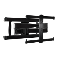
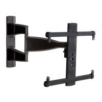
Arm Assembly
Wall Plate Screws
and Washers
Locking Screw
Cable Covers
Cover Plates
Hex Key
24 x1
25 x4 26 x4
30 x1
31 x2
27
x1
28 x2
29 x2
 Loading...