Service Manual MS CE25FN1-E
14
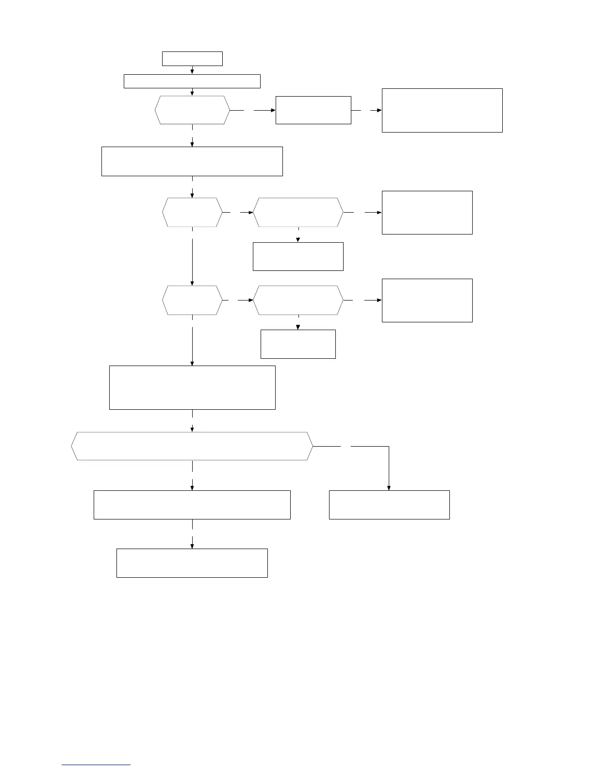
ERROR_4
Put a jumper between B-E of Q850 (N.1)
Check +B4
(cathode of D852)
Probably:
* IC701failure
* Shortcircuit or over consumptiom
* IC850 does not work OK
Check +8V
(N.2)
In models with Active 3D Surround: Check +9V
In models without Active 3D Surround:Skip this step
OK
OK
Check +5V
OK
NG Yes
Check the path of
Q853, Q854 and Q856.
No
Is the voltage level
at pin 4 of IC854
greater than 2V?
Probably:
*There is not +B7at IC854
*Shortcircuit in +5V
*IC854 failure
Yes
Check D875 and R869
No
NG
* Check the B_HIGH signal and his path until Q850
* Check the pull-up of the pin 52 of IC100
OK
Probably:
*There is not +B6 at IC853
*Shortcircuit in +8V
*IC853 failure
Check the rectifier
diodes
NG OK
Check with the oscilloscope that the rise time of B1 in the stand-by
to "ON" sequence is less than 160 ms (without the jumper in Q850)
Check that the rise time of +8V is less than 20 ms
Check Q856 and its components at the base
Check C809 and B8 source
OK
OK
NG
NG
N.1: Once the power supply is repaired, remove the jumper. Without it, the deflection does not start
N.2: Consider in this situation that the +8V source could be at 7,5 volts
Is the voltage level
at pin 4 of IC853
greater than 2V?