SERVICE FLASH (ADDITIONAL)
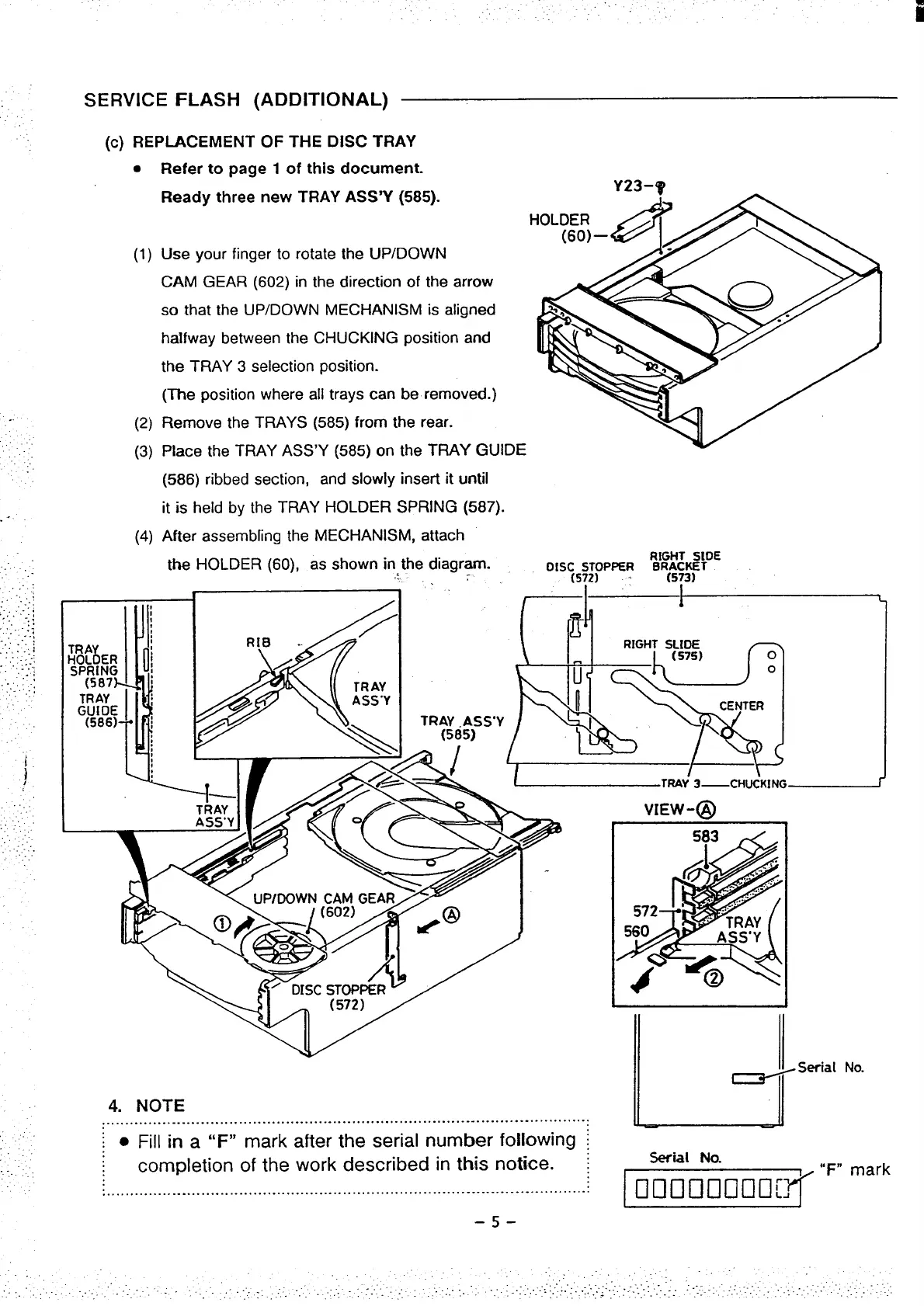
(c) REPLACEMENT OF THE DISC TRAY
●
(1)
(2)
(3)
(4)
Refer to page 1 of this document.
.-
Ready three new TRAY ASS’Y (585).
Use your finger to rotate the UP/DOWN
CAM GEAR (602) in the direction of the arrow
so that the UP/DOWN MECHANISM is aligned
halfway between the CHUCKING position and
the TRAY 3 selection position.
(The position where all trays can be removed.)
Remove the TRAYS (585) from the rear.
Place the TRAY ASS’Y (585) on the TRAY GUIDE
(586) ribbed section, and slowly insert it until
it is held by the TRAY HOLDER SPRING (587).
After assembling the MECHANISM, attach
the HOLDER (60), as shown in the diagram.
~.
I
-1
1
1
4. NOTE
.......................................................................................................
I
● Fill in a “F” mark after the serial number following ~
completion of
the work described in this notice. :
.......................................................................................................
–5-
I
Serial No.
~
“F”
mark

 Loading...