Do you have a question about the Sanyo DC-DA170 and is the answer not in the manual?
Details reception frequencies for FM, MW, and LW bands.
Lists channels, sampling frequency, and pick-up specifications.
Covers track system, frequency response, S/N ratio, and wow/flutter.
Outlines output power, inputs, outputs, and speaker system details.
Instructions for cleaning the optical lens using alcohol and a swab.
Procedures for adjusting CD player settings.
Steps to confirm tracking balance using an oscilloscope.
Steps to check the CD player's "eye" pattern using an oscilloscope.
Procedures for replacing tape heads and adjusting azimuth.
Methods for adjusting motor speed and checking mechanism torques.
Procedure for replacing the tape deck motor.
Lists packing materials and accessories for the product.
Details screws, washers, and other fixing components.
Lists parts related to the product's enclosure and internal chassis.
Lists various electrical components like cables, fuses, and connectors.
Lists components for the front printed wiring board.
Lists components for the CD printed wiring board.
Lists components for the UK version tuner printed wiring board.
Lists components for the XE version tuner printed wiring board.
Lists components for the amplifier printed wiring board.
Shows exploded view and parts for the tape mechanism.
Lists components for the power transformer printed wiring board.
Block diagram and pin description for IC201.
Block diagram and pin description for IC211.
Block diagram and pin description for IC601.
Block diagram and pin description for IC101.
Block diagram and pin description for IC410.
Block diagram and pin description for IC411.
Block diagram and pin description for IC412.
Block diagram and pin description for IC103.
Block diagram and pin description for IC415.
Block diagram and pin description for IC102.
Voltage tables for various integrated circuits.
Voltage table for various transistors.
Adjustment procedures for the FM tuner section.
Adjustment procedures for the MW tuner section.
Adjustment procedures for the LW tuner section.
Adjustment procedures for the FM tuner section (XE version).
Adjustment procedures for the MW tuner section (XE version).
| Brand | Sanyo |
|---|---|
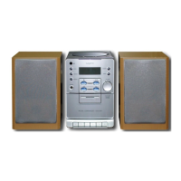
| Model | DC-DA170 |
| Category | Stereo System |
| Language | English |