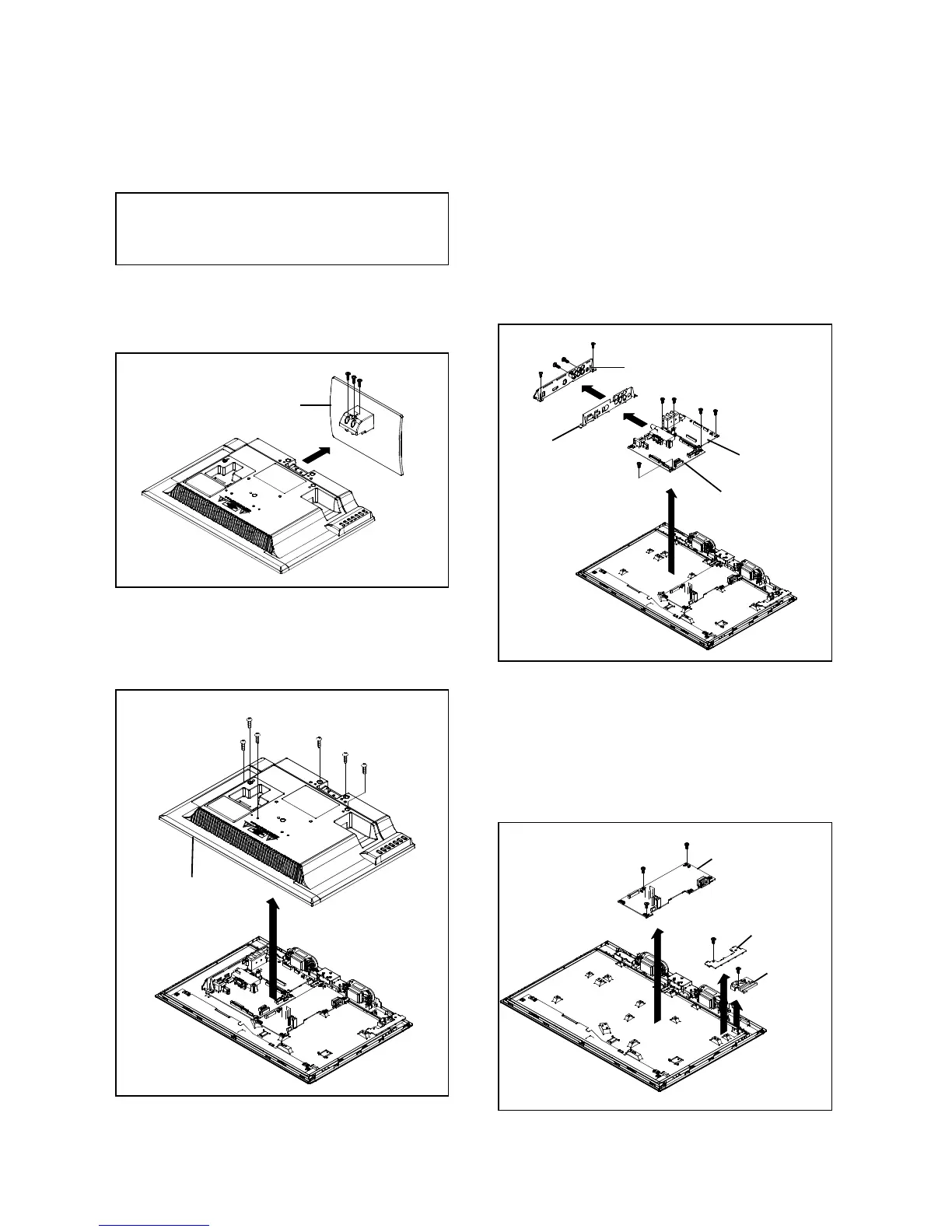
1. REMOVAL OF MECHANICAL PARTS
1-3: MAIN PCB / SIDE JACK PCB (Refer to Fig. 1-3)
AND P.C. BOARDS
1. Remove the 2 screws
CAUTION
3. Remove the Plate Jack in the direction of arrow
Be careful not to remove the FFC cable forcibly, because 4. Remove the Shield Jack in the direction of arrow
the FFC cable may be damaged. 5.
Disconnect the followin
7. Remove the Main PCB and Side Jack PCB in the direction
of arrow (C).
1.
Remove the 3 screws (1).
2.
Remove the Stand Ass'y in the direction of arrow
(1)
(1)
(1)
(1)
Stand Ass'y
(1)
(2)
(2)
(A)
Plate Jack
(B)
Shield Jack
(3)
(3)
(3)
(C)
Side Jack PCB
(3)
(3)
Main PCB
B1-1
1-2: BACK CABI ASS'Y
2. Remove the 5 screws (2)
3. Remove the Back Cabi Ass'
in the direction of arrow
2.
Disconnect the following connector: (CP7001).
3. Remove the Power PCB in the direction of arrow
4. Remove the screw (2).
5. Remove the O
eration PCB in the direction of arrow
.
7. Remove the Holder PCB in the direction of arrow
Fig. 1-4
Fig. 1-3
Fig. 1-1
Fig. 1-2
(1)
(2)
(2)
(2)
(1)
(1)
(1)
Power PCB
(2)
(2)
Back Cabi Ass'y
(2)
(3)
(A)
Operation PCB
Holder PCB
(B)
(C)
B1-1

 Loading...