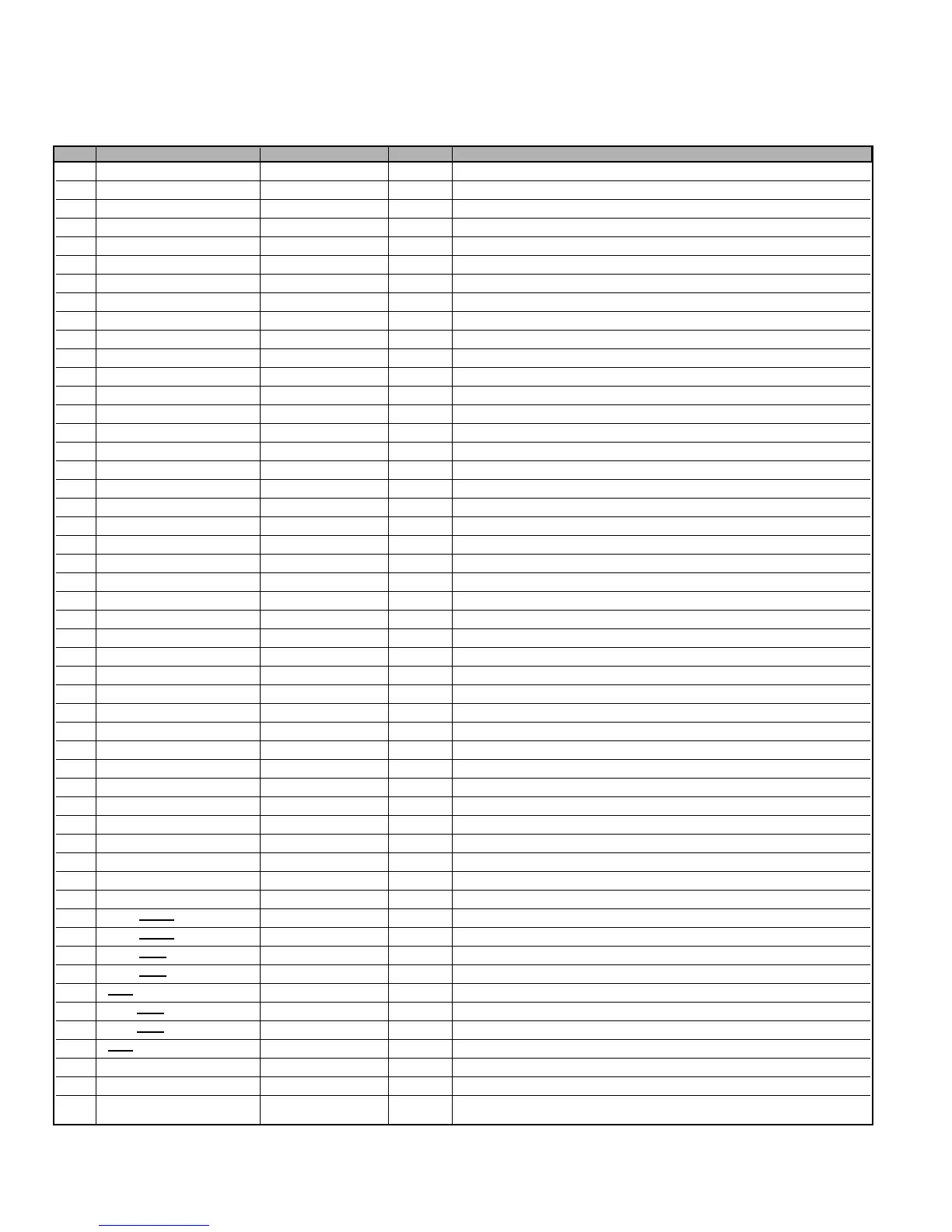
– 40 –
PIN IC specification Assignment I/O Explanation
1 P12/SCK0 REG SW4 OUT no use (REG SW4)
2 P13/SO1 REG SW5 OUT no use (REG SW5)
3 P14/SI1/SB1 IIC-BUS for NV I/O Data of IIC Bus Active ‘L’ for IIC data NV
4 P15/SCK1 IIC-BUS for NV OUT Clock of IIC Bus Active ‘L’ for IIC clock NV
5 P16/T1PWML REG SW2 OUT REG SW2 (ON : High OFF : Low)
6 P17/T1PWMH/BUZ REG SW3 OUT REG SW3 (ON : Low OFF : High)
7 PWM2 illumination OUT no use (illumination LED output )
8 PWM3 no use (PWR_DET) IN no use (PWR DET)
9 VDD2 Power IN IN VDD2 (5Vdc±10%)
10 VSS2 Vss IN GND (0Vdc)
11 P00 Category2 IN Hard option for category (See other sheet,Zoran/BRCM model)
12 P01 Category1 IN Hard option for category (See other sheet,Zoran/BRCM model)
13 P02 Category0 IN Hard option for category (See other sheet,Zoran/BRCM model)
14 P03 Panel Size2 IN Hard option for panel size (See other sheet,Zoran/BRCM model)
15 P04 Panel Size1 IN Hard option for panel size (See other sheet,Zoran/BRCM model)
16 P05/CKO Panel Size0 IN Hard option for panel size (See other sheet,Zoran/BRCM model)
17 P06/T6O LED CNTRL OUT LED Control output for Power indicater
18 P07/T7O TV Relay out OUT POWER Relay control output ON : High OFF : Low
19 P20/UTX/INT4/T1IN UART OUT OUT Output of UART(Digital Module microcomputer piece confidence )
20 P21/URX/INT4/T1IN UART IN IN Input of UART (Digital Module microcomputer piece confidence)
21 P22/INT4/T1IN PC Standby LED OUT LED control of PC Standby High_Noraml_Low
22 P23/INT4/T1IN Audio MUTE OUT Audio Mute MUTE ON : Low OFF : High
23 P24/INT5/T1IN Power Fail-2 IN IN no use (LVDS Power Fail input for LCD model)
24 P25/INT5/T1IN AMP_STBY OUT no use (AMP Standby control)
25 P26/INT5/T1IN HS_DET IN Detect H-Sync (Detect : High , PC Input)
26 P27/INT5/T1IN VS_DET IN Detect V-Sync (Detect : High , PC Input)
27 PB7 RESET_TV OUT RESET_TV => for DM Watch Dog Timer
28 PB6 Boot_SEL1 OUT no use (Starting DM S/W download-SEL1 for US1T model)
29 PB5 Boot SEL2 OUT no use (Starting DM S/W download-SEL2 for US1T model)
30 PB4 M_OUT MUTE OUT MUTE ON:Low OFF:High
31 PB3 LINE OFF_DET OUT Detect LINE OFF output(Detect: High -> Low)
32 PB2 Reserve OUT Reserve (Set Low level)
33 PB1 Reserve OUT Reserve (Set Low level)
34 PB0 Solution IN High:AMD Low:Zoran
35 VSS3 Vss IN GND (0Vdc)
36 VDD3 Power IN IN VDD3 (5Vdc±10%)
37 PC7 DBGP2 IN Terminal for De-Bug 3
38 PC6 DBGP1 I/O Terminal for De-Bug 2
39 PC5 DBGP0 I/O Terminal for De-Bug 1
40 PC4 CLK OUT Writing on bord (CLK)
41 PC3/AN11 DATA0 I/O Writing on bord (DATA0)
42 PC2/AN10 ENA/DATA1 I/O Writing on bord (ENA/DATA1)
43 PC1/AN9 Ack out OUT Ack output for factory mode
44 PC0/AN8
STATUS in IN Status input for factory mode
45 P86
/AN6 sensor in IN Light sensor input
46 P85/AN5 Reserve OUT (OPEN) (Set Low level)
47 P84/AN4 Panel Alarm IN no use (Panel Alarm)
48 P83/AN3 Power Fail-1 IN IN TV Power Error(3.6V less)/Others (3.6V over)
49 P70/INT0/T0LCP LINE OFF IN Detect AC Voltage Reduction (Normal : High)
50 P71/INT1/T0HCP CEC input IN CEC input
51 P72/INT2/T0IN CEC output OUT CEC output
System Control (CPU : IC800)
CONTROL PORT FUNCTIONS
 Loading...