– 6 –
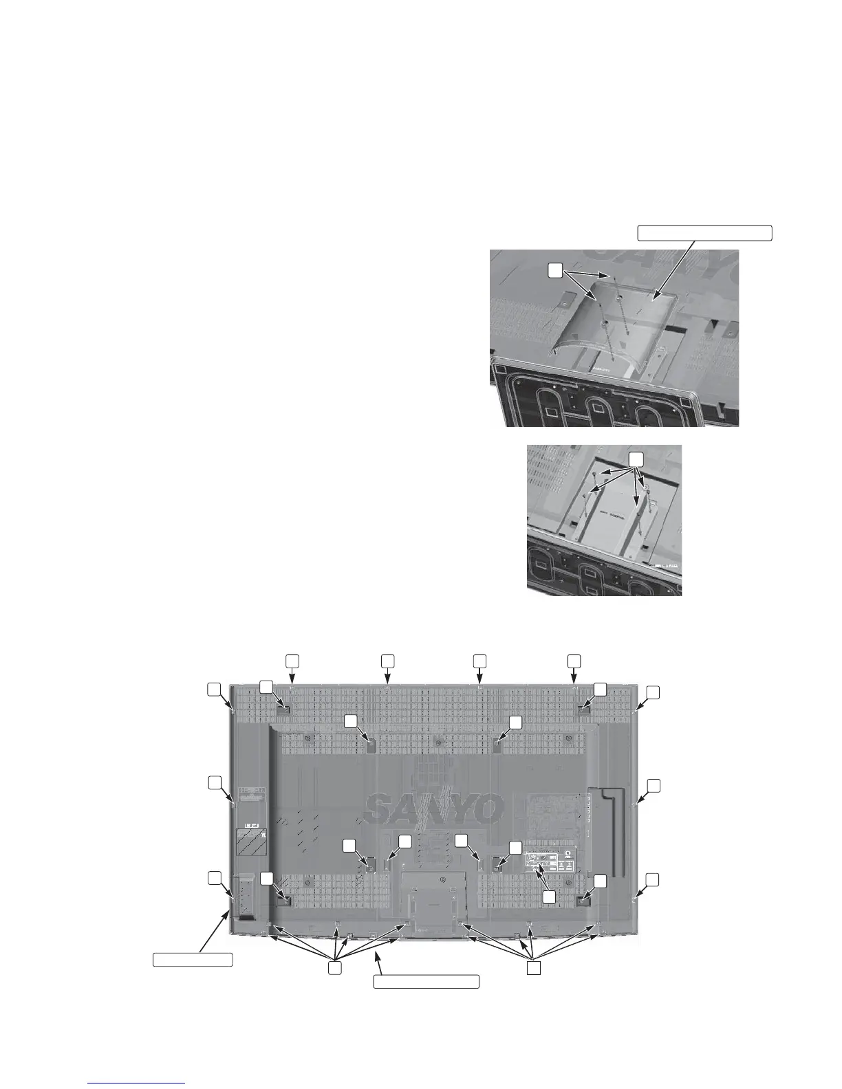
STAND REMOVAL
Note: Position TV face down on a padded or cushioned
surface to protect the screen and finish.
1. Remove 2 screws (D: 4x8) to take the stand base cover off.
2. Remove 4 screws (E: 4x10) to take the stand off.
MECHANICAL DISASSEMBLY
Stand Base Cover
D
E
CAUTION:
This LCD TV uses several different kinds of screws. Using the correct screw is necessary to prevent damage. Lead
wires must be redressed to their previous locations after servicing. The Earth sheet and gasket are provided to
prevent interference to other radio and television receivers. The Earth sheet and gasket should be returned to its
previous position after servicing.
B
D
B
C
D
C
C
C
C
C
C
C
C
CCC
D
D
D
D
B
B
F
Key SW Unit
AC Power Code
BACK CABINET REMOVAL
1. Remove 34 screws (C: 3x14, 22pcs; D: 4x8, 6 pcs; F: 3x12,
2 pcs; B: 6x12, 4 pcs.)
2. Lift the back cabinet, and remove the connector of the
KEY SW unit.
3. Remove the AC power cord from the back cabinet.
4. Take the back cabinet off.
NOTE:
Speaker is not fixed with screw.
 Loading...