GENERAL
This set has an on-screen Service Menu system included in the CPU that allows remote operation for most of the service adjustments.
To enter the Service Menu, first disconnect the AC power cord. Then while pressing the MENU key on the front control panel, recon-
nect the AC power cord. The adjustments can now be made with the remote control or front control panel keys.
ON-SCREEN SERVICE MENU SYSTEM
1. Enter the Service Menu:
• While pressing the MENU key on the front control panel, reconnect the AC
power cord. The Service Menu Display will now appear. (See Figure 1.)
2. Service Adjustments:
• Press the ▲ or ▼ key to select the desired service menu item you
want to adjust. (See page 5 for On-screen Service Menu.)
• Use the + or – key or number keys to adjust the data.
The + or – keys will increase or decrease the data sequentially.
The number keys (0 ~ 7) toggle only their respective bits between
1 and 0 and are used to change the Sub-Address. For example to
change bit 5 press the number 5 key. (See below)
3. Exit from the Service Menu:
• Press the MENU key to turn off the Service Menu display.
SERVICE ADJUSTMENTS
— 3 —
IC802 (EEPROM) REPLACEMENT
When IC802 (EEPROM) is replaced, IC801 (CPU) will automatically write the initial reference data into IC802 for basic TV operation.
However, the bus data should be checked and some bus data should be set up before attempting the service adjustments.
(See pages 5 – 7, Table 1, for detailed bus data information.)
INITIAL BUS DATA SETUP
Note: When IC802 (EEPROM) is replaced, change the following initial reference data for proper TV operation before
attempting service adjustments.
1. Disconnect the AC power cord (AC 120V line).
2. While pressing the MENU key, reconnect the AC power cord. The Service Menu display will now appear.
3. Select NO. 3C SCO (Sub Color) with ▲ or ▼ key. Adjust the data with + or – key for 17.
4. Select NO. 3D STI (Sub Tint) with ▲ or ▼ key. Adjust the data with + or – key for 10.
5. Select NO. 3F SSH (Sub Sharpness) with ▲ or ▼ key. Adjust the data with + or – key for 04.
6. Select NO. 40 AFC6HFR (AFC / H Frequency) with ▲ or ▼ key. Adjust the data with number keys for BF.
7. Select NO. 41 VTR7HP (V Trans / H Phase) with ▲ or ▼ key. Adjust the data with + or – key for 0E.
8. Select NO. 42 VS (V Size) with ▲ or ▼ key. Adjust the data with + or – key for 35.
9. Select NO. 43 VSP7VPO (V Sync Sep / V Position) with ▲ or ▼ key. Adjust the data with number keys for 15.
10. Select NO. 45 VC5LVL (V Compresion / V Lin Bottom) with ▲ or ▼ key. Adjust the data with number keys for 9F.
11. Select NO. 4A RD (Red Drive) with ▲ or ▼ key. Adjust the data with + or – key for 3A.
12. Select NO. 4C BD (Blue Drive) with ▲ or ▼ key. Adjust the data with + or – key for 3A.
13. Select NO. 50 OSD (OSD Contrast) with ▲ or ▼ key. Adjust the data with + or – key for 0A.
14. Select NO. 54 FLS (Y/C Filter Mode) with ▲ or ▼ key. Adjust the data with + or – key for 83.
15. Select NO. 57 YGM6DCR4BSS2BSG (Y Gamma / DC Reset / Black Steak Start / Black Streak Gain) with ▲ or ▼ key.
Adjust the data with number keys for 61.
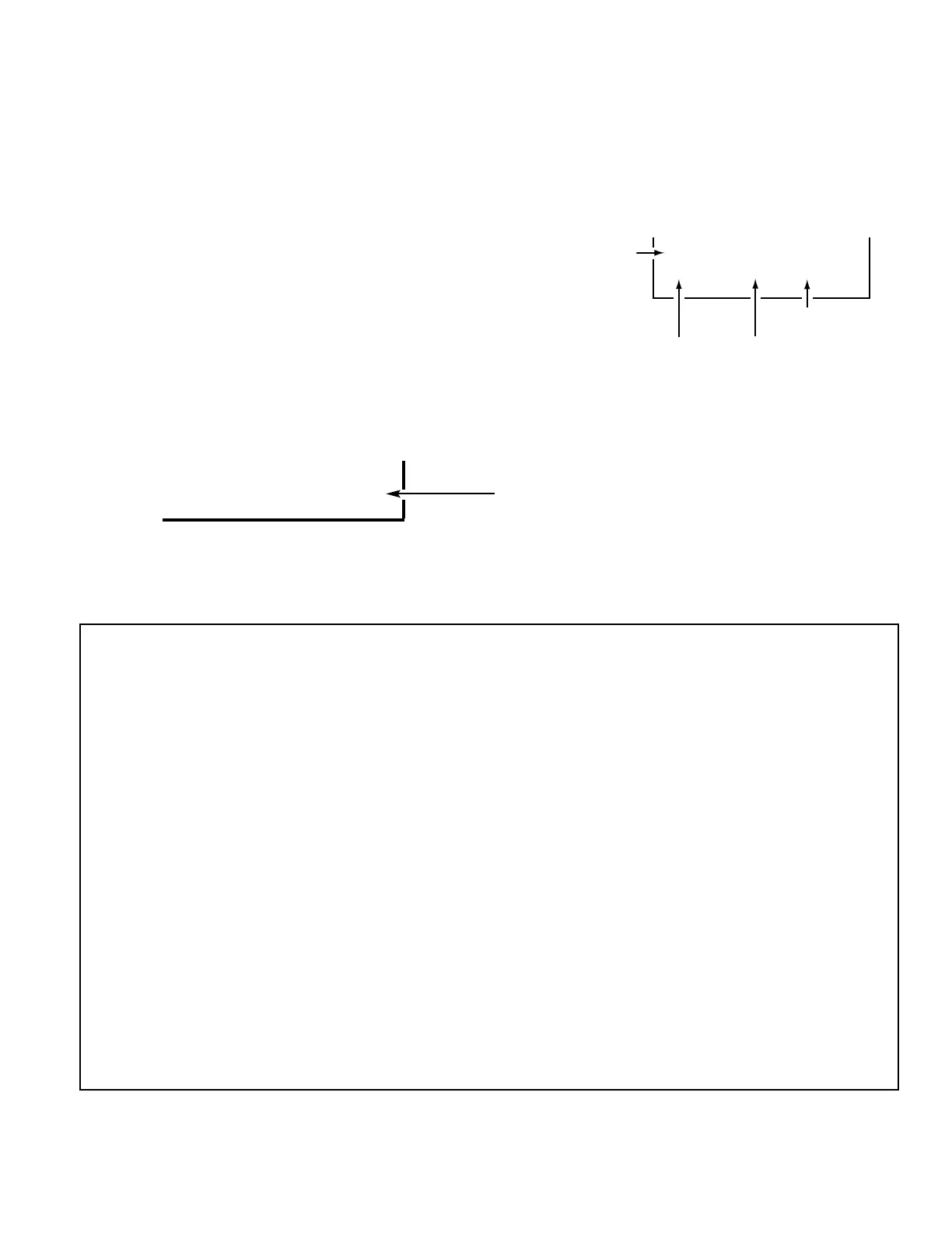
SCO
3C 17 00010111
Figure 1. Service Menu Display
ITEM NO.
TITLE
BINARY DATA
(8 bit)
HEX DATA
(b7) (b6) (b5) (b4) (b3) (b2) (b1) (b0)
0 1 0 1 0 1 1 0
BINARY DATA
(8 bit)
 Loading...