Fig. 2 System block diagram
4.4.2 Drive program and communication setup
4.4.2.1 Specific drive program must be set up for interfaces of PC and CA210, please refer to
detailed procedures as below:
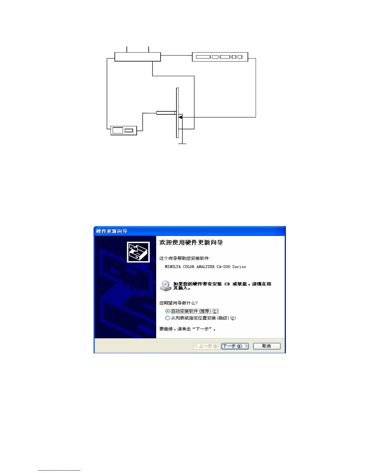
a) Power on CA210, a dialog box shown as Fig. 3 will display for the first installation after data line
is connected normally;
Fig. 3 Dialog box
b) Select option “Install from list or specific location (Advanced) (S).”, then press key “Next
step”, a dialog box shown as Fig. 4 will display;
RS232
 Loading...