Alignment instructions
2. Test equipment
VG-848 (VGA, YPbPr signal generator)
VG-849 (HDMI digital video signal generator)
CA210 (color analyzer)
3 Alignment flow
3.1 Voltage of power supply test
According to the wiring of “9224KH5201JL”, connect main board, power board and IR board
correctly, then switch on the main power and press key “standby” to turn on the set.
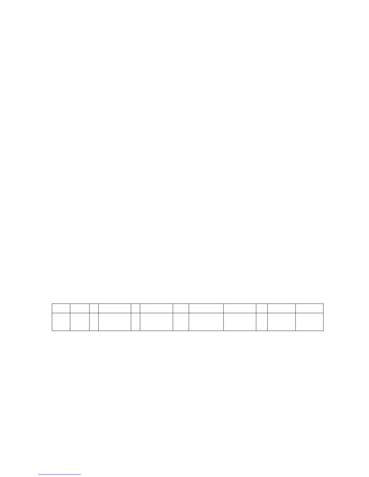
a) Test voltage of socket X401 each pin in turn, please refer to voltage values of Table 1:
Table 1 Voltage of X401 each pin
X108 Pin1 2 3 4 5 6
7 、8 9 、10
11 12 13
Vol.
>2.5
V
0
4.85 V ~
5.35 V
0
4.85 V ~
5.35 V
0 0
11.4 V ~
12.6 V
0
3.2 V ~
3.4 V
4.9 V ~
5.1 V
1. Safety Instructions
Be sure to switch off the power supply before replacing or welding any components or
inserting/plugging in connection wire Anti static measures to be taken (throughout the entire
production process!):
a) Do not touch here and there by hand at will;
b) Be sure to use anti static electric iron;
c) It’s a must for the welder to wear anti static gloves.
Please refer to the detailed list before replacing components that have special safety requirements.
Do not change the specs and type at will.
 Loading...