b) Communication connection
RS232 connective line should have dual female-head connected directly (commonly, 2# and 3#
of one head should be exchanged), only 2#, 3# and 5# need to be used.
4.4.2.4 Connect the output of VG848 to the input of TV.
Now there are input ports - AV, YPbPr, VGA and HDMI, which can be connected based upon
demand; if there are several input ports of AV, YPbPr, VGA or HDMI respectively, only connect to the
first input port;
4.4.3 Signal connection
Connect the channel required adjustment to VG848, if there are several channels for one sort of
signal, the first channel must be connected, for example: if AV has three channels - AV1, AV2, AV3,
and YPbPr has two channels - YPbPr1, YPbPr2, AV1 and YPbPr1 must be connected.
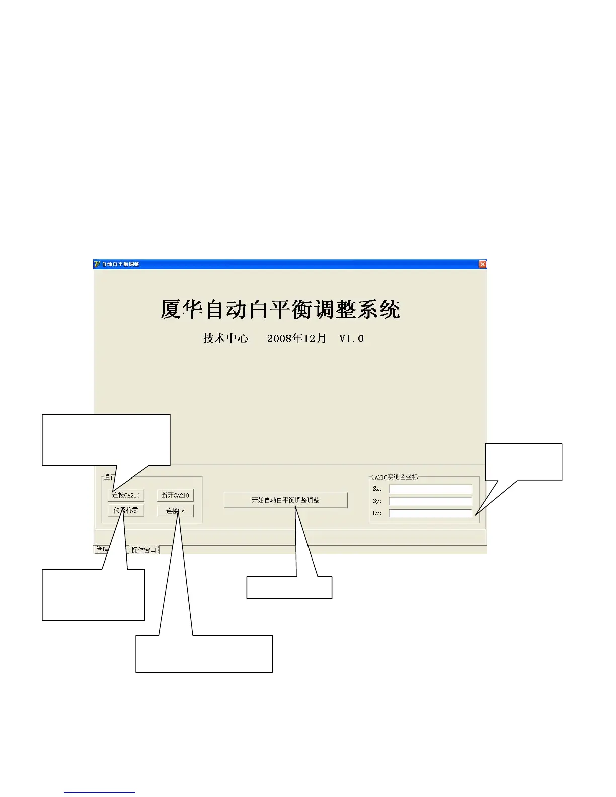
4.4.4 Adjusting interface shown as Fig. 13 and Fig. 14:
Fig. 13 Interface of Prima auto white balance adjusting system
Adjusting button
Connect to CA210 after
adjusting system opened
every time.
Calibrate value ”0”
after power-on every
time.
Connect to TV after adjusting
system opened every time.
Real chromatic
coordinates
 Loading...