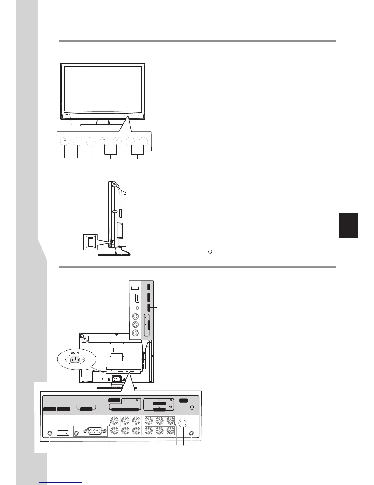
Identification of Controls
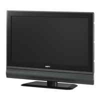
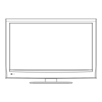
Main Unit (front/side view)
1. Remote sensor/Light sensor
2. Power indicator
Lights blue when in operating mode.
Lights red when in standby mode.
3. POWER
4. SOURCE
To access SOURCE menu
5. MENU
Press this button to access the main menu screen.
6. CH
Press these two buttons to directly change the TV channel;
In menu operations, these buttons serve as up/down buttons.
7. VOL+
Press the VOL+ or VOL– button to directly increase or decrease
the sound volume level;
In menu operations, these buttons serve as right/left buttons.
8. Power Switch
Note: B
Receives signals from the remote control. Do not block.
The light sensor will measure the room brightness, do not put anything
around the sensor.
Press this button to turn the unit ON from STANDBY mode. Press it
again to turn the set back to STANDBY.
^
/
^
/–
^
uttons on the TV control panel (CH / , VOL+/-, MENU,
^
SOURCE, POWER ) are touch buttons. First touch of the button will
illuminate it. Second touch will fulfill its function.
Main Unit (back view)
1. USB port: Connect a USB device to this port.
2. HDMI2: Connect an HDMI device to this jack.
3. MUSIC: Connect a MP3 player to this jack.
4. AV2 INPUT: Connect an AV device to these jacks.
5. RS-232: For service only. Do not use.
6. HDMI1: Connect an HDMI device to this jack.
7. PC IN D-SUB/AUDIO: Connect a computer to these jacks.
8. S/PDIF (coaxial): Connect a digital sound system to this jack.
9. COMPONENT IN: Connect a component video device to these
jacks.
10. AV1 INPUT: Connect an AV device to these jacks.
1 2
7
8
SOURCE MENU
CH VOL
SOURCE
MENU
CH VOL
+
3 4 5 6 7
1
2
3
4
14
AV OUT
AV1 IN
D-Sub
AUDI O
PC IN
RF
Y
HDMI 1
C /P
r r
C /P
b b
COMPONE NT IN
S/PDIF
RS-23 2
VI DEO
AUDIOAUDIO
VI DEO
AUDIO
VI DEO
L
R
AUDIO
AV 2 I N
US B
HD MI 2
MU SIC
5
6 7 8 9 10 11 12 13
11. AV OUTPUT: Connect a VCR to these jacks to
record programs.
12. RF: Connect an antenna or cable TV to this jack.
13. Headphone: Connect headphones to this jack.
14. AC IN: Plug the AC cord into this jack and into a
power outlet.
 Loading...