EasyManua.ls Logo

Sanyo LCD-40E40F - User Manual

Sanyo LCD-40E40F
56 pages
To Next Page IconTo Next Page
Loading...
1
FILE NO
SERVICE MANUAL
LCD TV
LCD-40E40F
PRODUCT CODE No.: 168234974 (3P AC Plug)
: 168234975 (2P AC Plug)
CHASSIS No.
SSB40SM-00
CHASSIS No.
SSB40SM-01
CHASSIS No.
SSB40SA-00
CHASSIS No.
SSB40SA-01
REFERENCE No.:
SM0945004-02
Question and Answer IconNeed help?

Do you have a question about the Sanyo LCD-40E40F and is the answer not in the manual?

Sanyo LCD-40E40F Specifications

General IconGeneral
BrandSanyo
ModelLCD-40E40F
CategoryLCD TV
LanguageEnglish

Summary

Safety Precautions

General Handling and Anti-Static Measures

Describes component replacement, tools, and anti-static procedures.

LCD Servicing Precautions

Covers high voltage, environment, liquid contact, smoke, wire handling, bending, static, wire care.

Transportation, Storage, and Display Handling

Covers shock, vibration, storage conditions, and ghost shadow.

Installation Precautions

Covers glass panel, screws, dust, partition plates, and cabinet protection.

Alignment Instructions

Test Equipment

Lists necessary equipment for alignment procedures.

Power Test Procedure

Details power board testing and voltage specifications.

Alignment Flow-Chart

Step-by-step visual guide for the alignment process.

Adjustment Procedures

Source Calibration

Procedure for calibrating input sources and entering factory mode.

Color Temperature Adjustment

Detailed steps for adjusting color temperature (Cool, Normal, Warm).

Factory Menu Operations

NVRAM Clear and Reset

Procedures for initializing settings and resetting the device.

Calibration and Testing Functions

Auto calibration, RF burn-in, and full power testing.

Shipping and Other Settings

Configuration for shipping and other menu items.

Dealer Mode and Performance Checks

Dealer Mode Functions

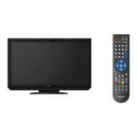
Description of volume lock, tuning lock, and start mode.

Input Signal Performance Checks

Procedures for checking TV functions via different inputs.

Software Update Instructions

Software Update Tool Setup

Configuration steps for the software update tool.

Firmware Update Process

Steps for selecting, starting, and completing firmware updates.

Working Principle Analysis

Signal Path Analysis

Analysis of PAL/NTSC, Composite, PC, and HDMI signal paths.

System Block Diagrams

Video Processing Block Diagram

Diagram of the main video processing IC.

Power Supply Block Diagram

Schematic overview of the power supply unit.

IC Features and Diagrams

SUNPLUS SPV7101 P Capabilities

Detailed features of the main processing IC.

Supporting IC Block Diagrams

Diagrams for Tuner, Audio Amp, and HDMI switch.

Wiring Connections

Main Board and Panel Module Wiring

Details for main board and panel connections.

Power Board and IR Board Wiring

Details for power board and IR connections.

Troubleshooting Guide

Fault Clearance and Common Issues

General steps for resolving common problems.

LED and Video Output Troubleshooting

Flowcharts for power LED and no video issues.

Audio Output Troubleshooting

Flowcharts for audio output issues.

Schematic Diagrams

Input Signal Schematics

Schematics for D-SUB, AV, and S-Video input ports.

HDMI and LVDS Schematics

Schematics for HDMI inputs and LVDS output.

Tuner and Audio Circuit Schematics

Schematics for tuner and audio processing blocks.

Control and Interface Schematics

IR, Flash, and Key Input Schematics

Schematics for IR, flash memory, and key input interfaces.

MCU and I2 C Control Schematics

Schematics for microcontroller and I2C communication.

Backlight and Power Control Schematics

Schematics for backlight and power management circuits.

Stand Installation and Removal

Cautions and Removal Procedure

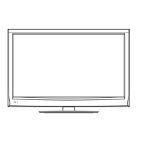
Precautions and steps for detaching the stand.

Stand Installation Procedure

Steps for attaching the stand to the TV.

Related product manuals