Part
Number
Cover of relay kit
14
Relay kit
13
Cover of control box
12
Earth (M5 with washer)
11
Terminal for communication line
10
Terminal for power line
9
Base of control box
8
Service panel
7
Discharge tube: ID1/2"
6
Suction tube: ID5/8"
5
Liquid tube : ID3/8"
4
Suspension hook
3
Liquid tube : ID1/4"
2
Types and specifications of
tubing connections
1
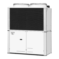
ATK-RZP56BAWB
Gas tube: ID1/2"
Specifications
12
1
2
6
4
5
10
1314
5-25/32
9-13/32
5-55/64
53/64 2-63/64
9-29/64
63/64
63/64
2-31/64
3-15/16
6-29/64
8-15/32
2-31/64
3-15/16
5-55/64
7/16
1-7/64
43/64
4-21/64 4-21/64
5-3/64
4-1/4
3-25/32
2-3/64
5-9/32
4-49/64
5-55/64
1-21/32
4-7/32
1-21/32
3-21/32
3-21/32
Unit: in.
3
7
9
11
8
ATK-RZP56BAWB
Compatibility
Power source
Power input
Net weight
Accessories
7.500 Total capacity of indoor units (BTU/h) < 19.000
Single-phase AC 208–230V 60Hz (supplied by indoor unit)
33 W max.
151.7 oz.
Washer x 2
Hanging hook
M4 screw x 4
Tapping screw x 4
Wire holder
3-WAY connect wire
ACC-3WAY-AAB (Solenoid Valve Relay Kit)
1-14. Optional Solenoid Valve Kit
Precautions on Installation of Solenoid Valve Kit
(1) Clean base metals thoroughly.
(2) Use proper ventilation to carry fumes away from the work area.
(3) Use a high quality silver based solder of at least 15 % silver.
(4) Heat the base materials broadly and uniformly.
(5) Take precautions not to overheat the device which could damage sensitive internal components.
(6) Insure compliance with all local codes!
W-3WAYECO-iU.indb15W-3WAYECO-iU.indb15 2009/11/1318:09:272009/11/1318:09:27
 Loading...