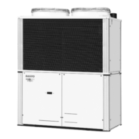
2-3. Dimensions of Wind Ducting
33-3/16 33-3/16 33-3/16
33-3/16
21
106-1/8
106-1/8
106-1/8
74-1/16
74-1/16
74-1/16
(32-1/8)
(32-1/8)
35-1/4
(Maximum bracket dimensions)
35
(Ceiling panel dimensions)
33-1/4
35-1/4
(Maximum bracket dimensions)
35
(Ceiling panel dimensions)
35
(Ceiling panel dimensions)
2
1
(32-1/8)
35
(Ceiling panel dimensions)
Ceiling panel
Front view Front viewRight side view Right side view
Ceiling panel
unit: in.
Note: Can be installed so that the air direction is to the front, right, left or rear direction.
31-1/8
5-3/4
5-3/4
113
(3-unit installation: maximum dimensions)
74-1/4
(2-unit installation: maximum dimensions)
7-7/8 7-7/8
36-1/4
(Installation hole pitch)
21
35
(Ceiling panel dimensions)
Front view Right side view
Top view
unit: in.
3-unit installation
Air direction: Front direction Air direction: Right direction
(Installation hole pitch)
31-1/8
(Installation hole pitch)
31-1/8
(Installation hole pitch)

 Loading...


