EasyManua.ls Logo

Sanyo SAP-KMRV94EH - User Manual

Sanyo SAP-KMRV94EH
28 pages
To Next Page IconTo Next Page
Loading...
Contents
Page
IMPORTANT!
Please Read Before Starting .................................. 2
1. GENERAL .......................................................... 3
1-1. Tools Required for Installation (not supplied)
1-2. Accessories Supplied with Unit
1-3. Optional Copper Tubing Kit
1-4. Type of Copper Tube and Insulation Material
1-5. Additional Materials Required for Installation
2. INSTALLATION SITE SELECTION ................... 4
2-1. Indoor Unit
2-2. Connecting Indoor Units
2-3. Outdoor Unit
2-4. Outer Dimensions of Outdoor Unit
2-5. Diagram of Outdoor Unit Installation
3. INSTALLATION PROCESS .............................. 13
3-1. Embedding the Tubing and Wiring
3-2. Drain Cap and Drain Elbow
3-3. Use of the Flaring Method
3-4. Flaring Procedure with a Flare Tool
3-5. Caution Before Connecting Tubes Tightly
3-6. Tubing Connections
3-7. Insulation of Refrigerant Tubing
3-8. Taping the Tubes
3-9. Finishing the Installation
4. AIR PURGING................................................... 16
! Air Purging with a Vacuum Pump (for Test Run)
! Pump Down
5. WIRING INSTRUCTIONS ................................. 19
5-1. General Precautions on Wiring
5-2. Recommended Wire Length and Diameter
5-3. Wiring System Diagram
5-4. How to Connect Wiring to the Terminal
5-5. Wiring Instructions for the Outdoor Unit
6. TEST RUN......................................................... 23
7. CONNECTING A HOME AUTOMATION
DEVICE ............................................................. 24
8. INSTALLATION CHECK SHEET ...................... 24
9. ELECTRIC WIRING DIAGRAM......................... 24
INSTALLATION INSTRUCTIONS
Model Combinations
Combine indoor and outdoor units only as listed below.
Indoor Unit Outdoor Unit
Combine indoor and outdoor units only as listed in
the combination tables for 2-room, 3-room or
4-room outdoor unit as shown in its respective
manual.
Power Source:
50 Hz, single-phase, 220 – 240 VAC
– Inverter Multi Split System Air Conditioner –
COOL/DRY/ HEAT Model
This air conditioner uses the new refrigerant R410A.
Be sure to read the yellow instruction sheet
attached to the outdoor unit for models using the
new refrigerant R410A.
The illustrations are based on the typical appearance of
a standard model. Consequently, the shape may differ
from that of the air conditioner that you are installing.
NOTE
Indoor unit A
Indoor unit B
Indoor unit C
Indoor unit D
Outdoor unit
Combination example
For Outdoor Unit
85264190442002 © SANYO 2008 SANYO Electric Co., Ltd.
Osaka, Japan
Español
Français
Deutsch Italiano
Português
EEÏÏÏÏËËÓÓÈÈÎο¿
English
SAP-KMRV74EH
SAP-KMRV94EH
SAP-KMRV124EH
SAP-KMRV76EH
SAP-KMRV96EH
SAP-KMRV126EH
SAP-KRV96EHDS
SAP-KRV126EHDS
SAP-KRV184EH
SAP-KRV244EH
SAP-KRV186EH
SAP-KRV246EH
SAP-CMRV1926EH
SAP-CMRV1936EH
SAP-CMRV2446EH
SAP-CMRV3146EH
08-253 CMRV3146EH_OU EN 10/14/08 2:39 PM Page a
Question and Answer IconNeed help?

Do you have a question about the Sanyo SAP-KMRV94EH and is the answer not in the manual?

Sanyo SAP-KMRV94EH Specifications

General IconGeneral
Star Rating3 Star
Noise Level (Outdoor Unit)52 dB
TypeSplit AC
RefrigerantR410A
Cooling Capacity2.5 kW
Power Supply50Hz

Summary

Model Combinations

IMPORTANT! Please Read Before Starting

General Precautions and Wiring Safety

Covers essential safety guidelines, electrical precautions, and grounding requirements for installation.

IMPORTANT! Please Read Before Starting

Installation Site Considerations

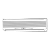
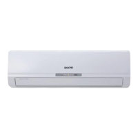
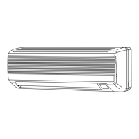
Provides guidance on selecting suitable locations for indoor and outdoor units, considering environmental factors.

Refrigerant Tubing and Servicing Safety

Details safe practices for refrigerant tubing connection, servicing, and environmental protection.

1. General

Tools, Accessories, and Materials

Lists required tools, supplied accessories, and additional materials needed for installation.

2. Installation Site Selection

Indoor Unit Placement Guidelines

Specifies AVOID and DO conditions for installing indoor units to ensure optimal airflow and performance.

Outdoor Unit and System Layout

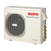
Covers outdoor unit placement, dimensions, and general installation diagrams for system configuration.

2. Installation Site Selection

2-2. Connecting Indoor Units

Provides detailed diagrams and instructions for connecting specific indoor units to outdoor units.

Tubing and Elevation Limits

Details maximum allowable tubing lengths and elevation differences between indoor and outdoor units.

2. Installation Site Selection

Connecting Indoor Units (Model Specific)

Illustrates connection diagrams for SAP-CMRV1936 and SAP-CMRV2446 indoor units to outdoor units.

2. Installation Site Selection

Connecting Indoor Units (Model Specific)

Illustrates connection diagrams for SAP-CMRV3146 indoor units to outdoor units.

2. Installation Site Selection

Connecting Indoor Units (Model Specific)

Illustrates connection diagrams for SAP-CMRV3146 indoor units to outdoor units.

2. Installation Site Selection

Connecting Indoor Units (Model Specific)

Illustrates connection diagrams for SAP-CMRV3146 indoor units to outdoor units.

2. Installation Site Selection

2-3. Outdoor Unit Placement

Specifies AVOID and DO conditions for installing outdoor units, including airflow and protection.

Outdoor Unit Installation Diagrams

Provides diagrams illustrating outdoor unit placement, clearances, and base requirements.

2. Installation Site Selection

2-4. Outer Dimensions of Outdoor Unit

Presents detailed dimensional drawings for various outdoor unit models, including service valve locations.

2. Installation Site Selection

2-5. Diagram of Outdoor Unit Installation

Shows a comprehensive diagram of outdoor unit installation, including clearances and connections.

3. Installation Process

Tubing and Wiring Preparation

Covers embedding tubing/wiring, drain connections, and the flaring method for refrigerant tubes.

3. Installation Process

Connecting Refrigerant Tubing

Details flaring procedures, pre-connection precautions, and tightening torques for refrigerant tube connections.

3. Installation Process

Insulation, Taping, and Finishing

Explains how to insulate, tape refrigerant tubing, and seal wall penetrations for final installation.

4. Air Purging

Air Purging with a Vacuum Pump

Describes the process of removing air and moisture from the refrigerant system using a vacuum pump.

Pump Down Procedure

Outlines the steps for performing pump-down to recover refrigerant gas without releasing it into the atmosphere.

4. Air Purging

Vacuum Pump Operation Details

Provides specific instructions for operating the vacuum pump and checking system pressure.

Service Valve Operation

Details the correct procedure for opening and closing service valves during air purging and leak testing.

4. Air Purging

Pump Down Procedure

Details the steps for performing pump-down during cooling operation to recover refrigerant.

5. Wiring Instructions

General Wiring Precautions

Covers essential safety rules and guidelines for wiring the air conditioning system correctly.

Recommended Wire Length and Diameter

Provides specifications for wire size, length, and fuse capacity based on unit model and wiring distance.

5. Wiring Instructions

5-3. Wiring System Diagram

Illustrates wiring system diagrams for connecting indoor units to the outdoor unit for different system configurations.

5. Wiring Instructions

5-4. How to Connect Wiring to the Terminal

Explains the correct method for connecting wires to terminal plates for both indoor and outdoor units.

5. Wiring Instructions

5-5. Wiring Instructions for the Outdoor Unit

Details wiring connections to the outdoor unit terminal board, grounding, and cable management.

6. Test Run

Performing a Test Run

Guides through the process of performing a test run for the air conditioner system and checking operation.

Checking Tubing and Wiring

Advises on how to check for errors in tubing and wiring connections during the test run.

7. Connecting a Home Automation Device

8. Installation Check Sheet

9. Electric Wiring Diagram

Indoor Unit Wiring Diagrams

Presents wiring diagrams for various indoor unit models, showing internal component connections.

9. Electric Wiring Diagram

Indoor Unit Wiring Diagrams

Continues to provide detailed wiring diagrams for different indoor unit models.

Outdoor Unit Wiring Diagrams

Outdoor Unit Wiring Diagrams

Meaning of Abbreviations

Related product manuals