Do you have a question about the Sanyo SAP-KMRV76EH and is the answer not in the manual?
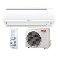
Detailed technical specifications for individual indoor and outdoor units, including capacity, power, and dimensions.
Technical details and specifications for key components within the outdoor unit, such as compressor, fan, and heat exchanger.
Specifications for sensors and other minor components used in the system.
Illustrates the path of refrigerant through the system during cooling, heating, and defrost cycles.
Graphs showing system performance characteristics at different temperature conditions.
Schematic diagrams detailing the electrical connections for the outdoor unit.
Describes the operational modes and basic functions of the air conditioning system.
Details safety features and operational protections implemented in the system.
Essential safety warnings and precautions for handling electronic components during service.
Explains how to interpret error codes indicated by lamps on the control board.
Procedures for checking the operational status and basic functions of the outdoor unit.
Guides for identifying problems by inspecting individual components of the system.
Specific troubleshooting steps for diagnosing issues with the fan motor.
Information on the properties and handling requirements of R410A refrigerant.
A pre-service checklist covering tools and preparations, especially for R410A.
Lists specialized tools required for servicing systems using R410A refrigerant.
Guidance on proper procedures for installing refrigerant tubing connections.
Steps for diagnosing and replacing a malfunctioning compressor.
Procedure for detecting, repairing, and recharging refrigerant after a leak.
Instructions for adding refrigerant, including proper state and amount.
Guidelines for adapting existing systems for R410A or replacing components.
List of tools needed for installation that are not included with the unit.
Details of parts and accessories provided in the unit packaging.
Information on available optional kits for refrigerant tubing installation.
Specifies the types and dimensions of copper tubing and insulation required.
List of supplementary materials needed for proper installation.
Guidelines for selecting an appropriate installation location for the indoor unit.
Instructions on how to connect multiple indoor units to a single outdoor unit.
Recommendations for selecting an optimal installation site for the outdoor unit.
Diagrams showing the physical dimensions of the outdoor units.
Visual guide illustrating the placement and connections for outdoor unit installation.
Steps for routing and securing refrigerant tubing and electrical wiring.
Details on installing drain components for condensate removal.
Explanation of the flaring technique used for connecting refrigerant tubes.
Step-by-step guide on performing flaring for tube connections.
Important warnings regarding dust prevention and lubricant application before tightening tubes.
Procedures for making secure and leak-free connections of refrigerant tubing.
Guidelines for insulating refrigerant tubes to prevent heat loss and condensation.
Instructions for taping refrigerant tubes and wiring bundles for protection.
Final steps to seal openings and complete the installation.
Procedure for removing air and moisture using a vacuum pump.
Method for recovering refrigerant gas from the system before relocation or disposal.
Essential safety rules and general guidelines for electrical wiring.
Guidance on selecting appropriate wire sizes and lengths based on regulations.
Diagrams showing the electrical connections between indoor and outdoor units.
Detailed instructions on properly connecting wires to terminal blocks.
Specific steps for wiring the outdoor unit, including grounding and cable management.
Procedures for conducting a functional test of the installed system.
Steps to verify the correctness of tubing and wiring connections after installation.
| Star Rating | 3 Star |
|---|---|
| Cooling Capacity | 6450 W |
| Refrigerant | R32 |
| Type | Split System |
| Power Supply | 230 V, 50 Hz |