A
Amanda CooperAug 3, 2025
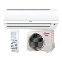
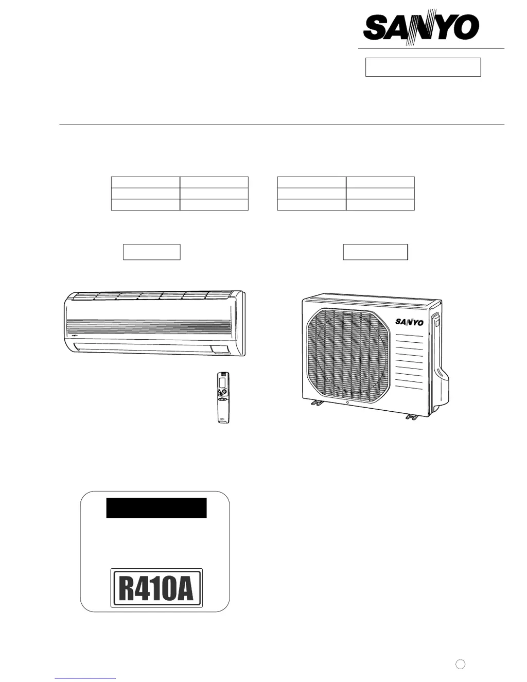
What to do if my Sanyo SAP-KRV93EH Air Conditioner malfunctions due to high-frequency noise?
- EErika AdamsAug 4, 2025
If your Sanyo Air Conditioner malfunctions due to abnormal signal pulses caused by high-frequency noise, especially if you are near broadcast stations with strong electromagnetic waves, amateur radio stations, electronic sewing machines, or arc-welding machines, insulate for noise or increase the distance from the noise source. You can also use shielded wires or move the unit away from the noise source.