EasyManua.ls Logo

Sanyo SAP-KRV96EH User Manual

Sanyo SAP-KRV96EH
65 pages
To Next Page IconTo Next Page
Page #1 background imageLoading...
Page #1 background image
TECHNICAL & SERVICE MANUAL
SAP-KRV96EH + SAP-CRV96EH
SAP-KRV126EH + SAP-CRV126EH
DC INVERTER SPLIT SYSTEM AIR CONDITIONER
Indoor Model No.
SAP-KRV96EH
SAP-KRV126EH
Product Code No.
1 852 346 74
1 852 346 75
FILE NO.
Outdoor Model No.
SAP-CRV96EH
SAP-CRV126EH
Product Code No.
1 852 346 81
1 852 346 82
REFERENCE NO. SM700728
Destination: Europe
A
I
R
C
O
N
DITIONER
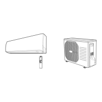
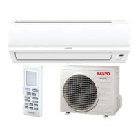
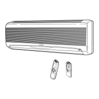
Indoor Unit Outdoor Unit
SAP-KRV96EH
SAP-KRV126EH
SAP-CRV96EH
SAP-CRV126EH
RoHS
WARNING
This product does not contain any hazardous substances prohibited by the RoHS Directive.
Compliance with regulation 842/EC/2006, Article 7(1) requirements
Do not vent R410A into the atmosphere:
R410A is a fluorinated greenhouse gas, covered by the Kyoto Protocol,
with a global warming potential (GWP) = 1975.
• You are requested to use RoHS compliant parts for maintenance or repair.
• You are requested to use lead-free solder.

Table of Contents

Questions and Answers:

Sanyo SAP-KRV96EH Specifications

General IconGeneral
BrandSanyo
ModelSAP-KRV96EH
CategoryAir Conditioner
LanguageEnglish

Summary

1. OPERATING RANGE

2. SPECIFICATIONS

2-1. Unit Specifications

Lists essential performance, electrical, and dimensional details for both indoor and outdoor units.

2-2. Major Component Specifications

Details specifications for key components like control PCB, fan motor, and heat exchanger coil.

2-3. Other Component Specifications

Presents performance data for sensors, showing resistance vs. temperature characteristics.

3. DIMENSIONAL DATA

4. REFRIGERANT FLOW DIAGRAM

4-1. Refrigerant Flow Diagram

Shows the complete refrigerant circuit, including key components and flow direction for cooling and heating.

5. PERFORMANCE DATA

5-1. Temperature Charts

Charts showing cooling and heating characteristics like pressure, current, and discharge air temperature.

5-2. Air Throw Distance Charts

Graphs illustrating air throw distance based on flap angle and air velocity for cooling and heating.

6. ELECTRICAL DATA

6-1. Electrical Characteristics

Lists running amperes and power input for indoor, outdoor, and complete units under different conditions.

6-2. Electric Wiring Diagrams

Provides wiring diagrams for the indoor unit, showing connections for various components.

7. INSTALLATION INSTRUCTIONS

7-1. Installation Site Selection

Advises on proper placement of the indoor and outdoor units, avoiding specific environmental factors.

7-2. Recommended Wire Length and Diameter

Specifies guidelines for wire sizing and length for power supply and control wiring.

7-3. Remote Control Unit Installation Position

Details recommended and prohibited locations for mounting the remote control unit.

7-4. How to Test Run the Air Conditioner

Step-by-step instructions for performing a test run of the air conditioning system.

7-5. Removing and Installing the Grille

Provides instructions for safely removing and reattaching the front grille for access.

8. MAINTENANCE

8-1. Address Setting of the Remote Control Unit

Explains how to set addresses for multiple remote controllers to prevent interference.

8-2. Disconnecting and Connecting Positive Connector for Outdoor Unit

Illustrates the correct procedure for disconnecting and connecting electrical connectors.

9. FUNCTIONS

9-1. Operation Functions

Details functions like Emergency Operation, AUTO mode, SENSOR DRY, and PAM-a control.

9-2. Protective Functions

Explains built-in safety features such as overload prevention and freeze prevention.

10. TROUBLESHOOTING

10-1. Precautions before Performing Inspection or Repair

Lists safety precautions to follow before starting any inspection or repair work.

10-2. Method of Self-Diagnostics

Provides a procedure to activate and interpret the unit's self-diagnostic mode for fault finding.

10-3. Checking the Indoor and Outdoor Units

Outlines steps to check basic operation of indoor and outdoor units using test run modes.

10-4. Noise Malfunction and Electromagnetic Interference

Discusses potential noise issues and electromagnetic interference and their solutions.

11. CHECKING ELECTRICAL COMPONENTS

11-1. Measurement of Insulation Resistance

Explains how to measure insulation resistance of power cords and unit components.

11-2. Checking Continuity of Fuse on PCB Ass'y

Describes the method for checking the continuity of fuses on the Printed Circuit Board Assembly.

12. REFRIGERANT R410A

12-1. Characteristics of New Refrigerant R410A

Details the composition, properties, and handling precautions for R410A refrigerant.

12-2. Checklist before Servicing

Provides a checklist of important points to consider before performing service on the unit.

12-3. Tools Specifically for R410A

Lists specialized tools required for servicing units using R410A refrigerant.

12-4. Tubing Installation Procedures

Outlines procedures for installing refrigerant tubing, including necessary precautions.

12-5. In Case of Compressor Malfunction

Describes the procedure for replacing a malfunctioning compressor.

12-6. In Case Refrigerant is Leaking

Details the steps for detecting, repairing, and recharging refrigerant after a leak.

12-7. Charging Additional Refrigerant

Explains how to charge additional refrigerant, especially when tubes are extended.

12-8. Retro-Fitting Existing Systems

Provides guidance on adapting existing systems for R410A, including tubing considerations.

APPENDIX INSTRUCTION MANUAL

Related product manuals