Separately sold parts
F - 4
2. System Configuration
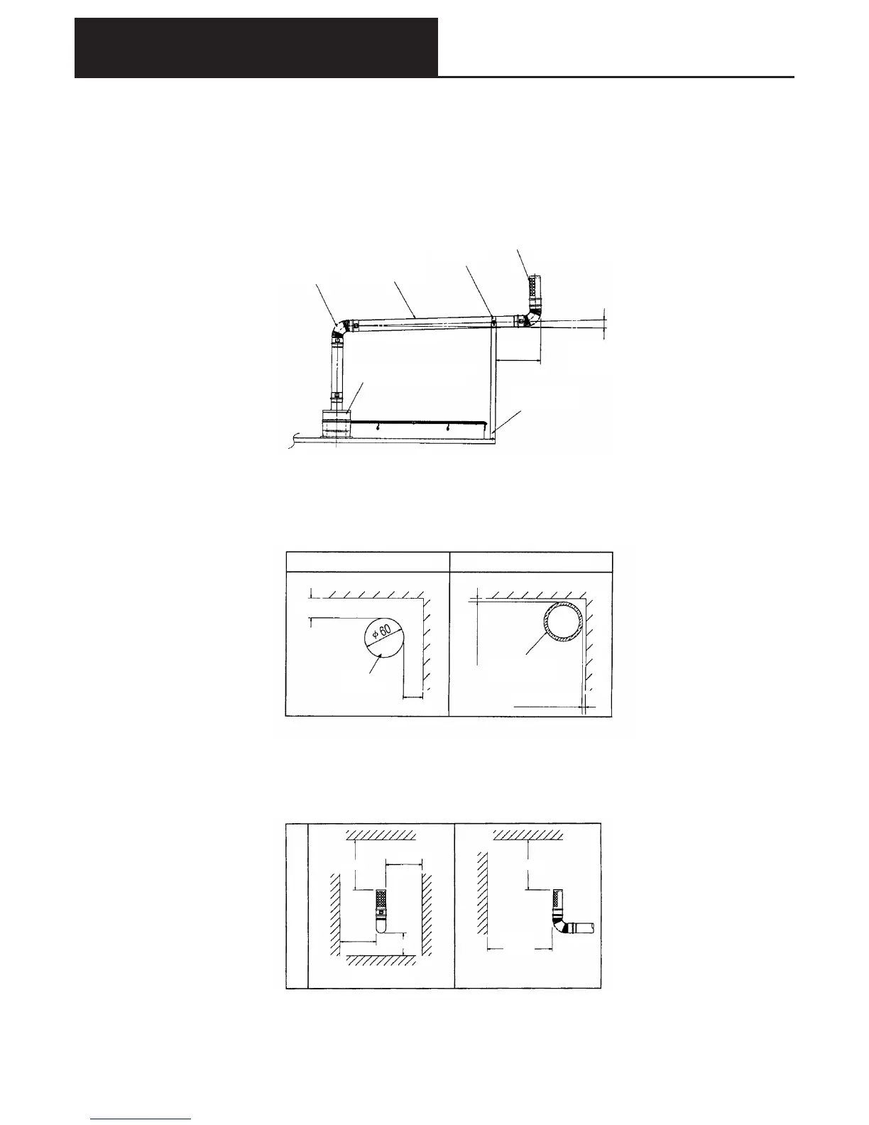
ONJ pipe
45 ‹ elbow
90 ‹ elbow
ONJ pipe
Straight pipe
Slide pipe
Split halves
Exhaust gas top
Orientation of opening
Upward slope
(3/100 or greater)
Adaptor for exhaust
gas extension
500mm
or less
Support legs
With no thermal insulation
With thermal insulation
30 or more
Not contacting
Exhaust gas pipe
Thermal insulation
thickness 20 or more
Not contacting
Horizontal one directional outlet
300 or more 300 or more
600
or more
150 or more
150
or more
Down
●Method of securing the exhaust gas pipe
1) For securing the exhaust gas pipe, use the installation fittings (legs, split halves) and fit on site. Using
the bolts/screws of the unit top plate secure the pipe. Refer to Figure 7 for an example.
2) Secure the exhaust gas pipe extending from the main body of the unit to the external wall or other
suitable location, using installation fittings every 1.5-2.0m.
3) The limiting distance from the final securing location to the end of the exhaust gas extension pipe shall
be 500mm or less. Refer to Figure 7.
Fig. 7
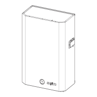
● Separation distance of the exhaust gas pipe
The separation distance (mm) of the exhaust gas pipe from “building parts with finishes made from flammable
materials, non-flammable materials, or quasi-flammable materials” shall be as shown in Figure 8.
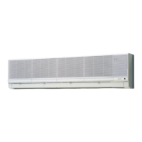
● Separation distance of exhaust gas top
The separation distance (mm) of the exhaust gas pipe opening from “building parts with finishes made from
flammable materials, non-flammable materials, or quasi-flammable materials” shall be as shown in Figure 9.
Figure 8(Space part)
<Reference> The dimensions within the ( )are the distances for the case where a heat-proof board is installed,
and “building parts are effectively finished with non-flammable materials.
Fig. 9(Separation distance around the exhaust gas top)