III - 37
3
SM830063
Service Procedures
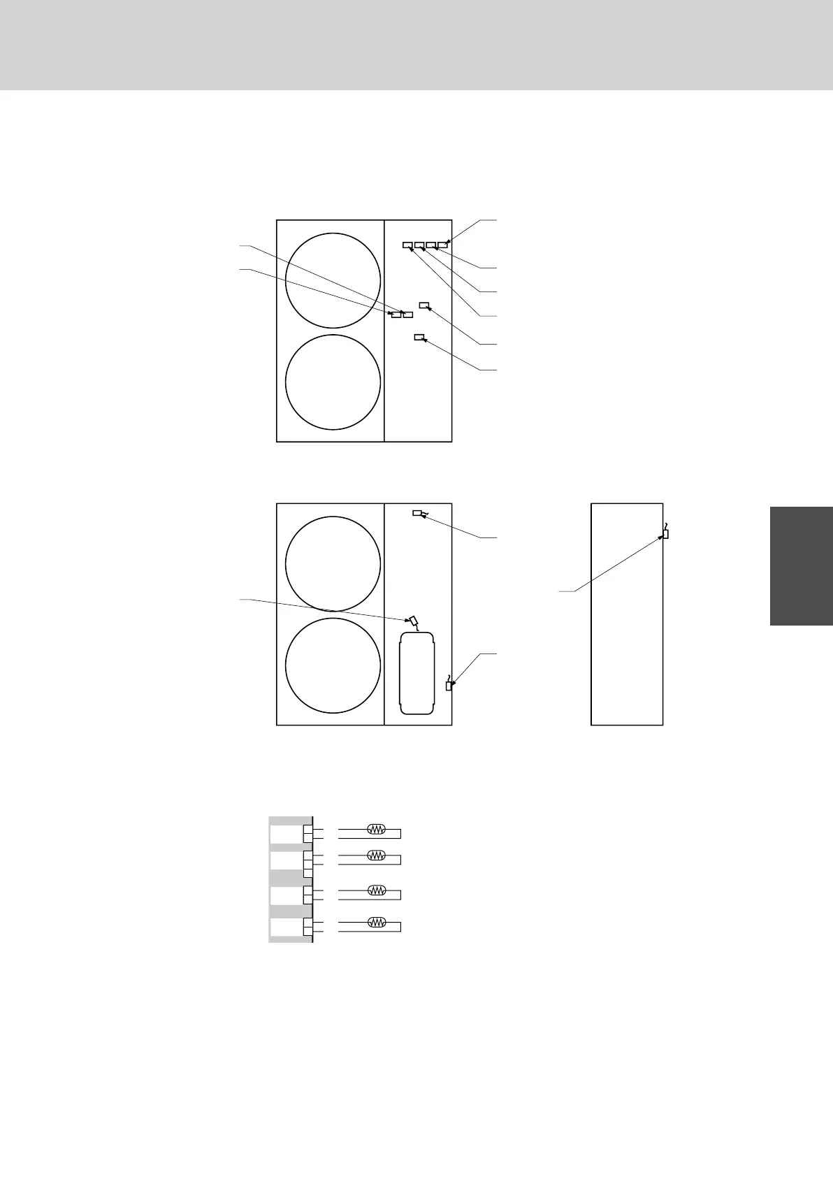
2. Sensor and Solenoid Layout Diagram
2-1. Outdoor unit
7 SPW-CR363GVH8, SPW-CR363GV8
7 SPW-CR483GVH8, SPW-CR483GV8
2
1
2
3
1
2
1
WHT
WHT
BRN
BRN
BLK
BLK
DISCH
2P(WHT)
EXG
3P(BRN)
2
1
BLK
BLK
EXL
2P(BLK)
AIR TEMP
2P(RED)
(DISCHARGE PC SENSOR )
(COIL GAS SENSOR*)
(COIL LIQUID SENSOR)
(AIR SUCTION TEMP)
1570_THS_I
TH1
TH2
TH5
TH3
Note) * is only for Heat pump type
1569_M_I
High Pressure Valve
L1 INJ. Valve (LIV)
Save Valve (SAVE)
Discharge PC Sensor
(TH1)
Low Pressure Valve (LPV1)
Low Pressure Valve (LPV2)
Low Pressure Valve (LPV3)
Four Way Valve (20S)
Motor Operated Valve*
Coil GAS Secsor
(TH2)*
Air Suction TEMP
(TH4)
Coil Liguid Sensor
(TH3)
Compressor
 Loading...
