CONNECTIONS (Fig. 3)
TO USE YOUR UNIT PROPERLY AND SAFELY
- If water should enter the unit, electrical shock or
malfunction may result. Always use it in a place where
there is low humidity and little dust.
- Do not use where there are extremes of temperature
(below 5°C or exceeding 35°C) or where direct sun-
light may strike it.
- Because of the CD player’s extremely low noise and
wide dynamic range, there might be a tendency to
turn the volume on the amplifier unnecessarily high.
Doing so may produce an excessively large output
from the amplifier which could damage your speak-
ers.
- Sudden changes in the ambient temperature may
cause condensation to form on the optical lens inside
the system. If this happens, take out the disc, leave
the system with the disc table extended for about 1
hour, and then proceed to operate.
CAUTION -- USE OF CONTROLS OR ADJUSTMENTS
7 PERFORMANCE OF PROCEDURES OTHER THAN
[ROSE SPECIFIED IN THE OPERATING INSTRUCTIONS
MAY RESULT IN HAZARDOUS RADIATION EXPOSURE.
THE COMPACT DISC PLAYER SHOULD NOT BE AD-
JUSTED OR REPAIRED BY ANYONE EXCEPT PROP-
ERLY QUALIFIED PERSONNEL.
BEFORE USE
Be sure to remove two screws (located on the rear of the
unit) as shown in Fig. 2. (The removed screws should be
retained.) Also remove the caution sheet putting on the
disc table.
Channel step select switch (CHANNEL STEP)
Set this switch (located on the rear of the unit) to 9 kHz
or 10 kHz, according to whether your local MW broad-
t system is organized in 9 kHz or 10 kHz steps.
Note:
Before operating the switch, be sure to disconnect the
mains lead.
Before transportation
1. Turn on the power and remove all discs from the trays.
2, Close the disc table.
3. Press the PLAY/PAUSE switch of the CD player. Check
that “no dlSC” appears on the CD display.
4. Turn off the power and disconnect the mains lead.
5. Secure two screws as shown in Fig. 2.
Power supply
Before use, set the VOLTAGE SELECTOR on the rear of
the unit to the position which corresponds tothevoltage
in the area of use. Use an ordinary screwdriver or similar
implement to make the setting, as shown in Fig. 4.
Connect the mains lead to an AC wall outlet.
Note:
Do not connect the mains lead to an AC outlet until all
connections have been made.
The unit is not disconnected from the mains unless it is
unplugged from the AC outlet.
Aerials (Fig. 5)
FM aerial
In areas close to a transmitter the simple indoor aerial
(supplied) is sufficient to receive FM broadcasts and
should be connected to the FM aerial terminal. In fringe
areas or where reception is distorted or noisy, an FM
outdoor aerial (not supplied) should be connected in-
stead of the indoor aerial. The terminals will accept 75-
ohm coaxial cable.
SW aerial
For SW reception, connect an SW aerial lead (not sup-
plied) to the SW aerial terminal, If further improved re-
ception is required, a SW outdoor aerial should be em-
ployed. Consult your dealer.
MW/SWl loop aerial
Assemble the loop aerial (supplied) as shown in Fig. 6a.
Unwind the aerial wires (about 3turns) and then connect
them to the AM LOOP ANT. terminals.
Place the loop aerial in a position which yields the best
MW/SWl reception, or attach the loop aerial to a wall or
other surface as shown in Fig. 6b.
Note:
Noise can affect the operation of the system if the aerial
is positioned close to the system or a TV set. Place it as
far away as possible.
ConsuIt with your dealer if you have any queries or
questions related to the selection, installation and con-
nection of aerials.
Speaker terminais (SPEAKERS)
These terminals will accept speakers of 8 ohms mini-
mum impedance. The speaker wires should be con-
nected to the speaker terminals with the proper poiarity.
The red terminals are (-t) positive and black terminals
are (-) negative (Fig. 7).
Note:
With incorrect poiarity connections, proper stereo repro-
duction cannot be obtained.
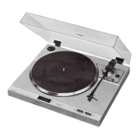
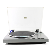
Phono input sockets (PHONO) and DC 12V socket
Connect the output leads and power suppiy lead of the
SANYO TP-XI 000 turntabie to the PHONO sockets and
DC 12V socket of the unit respectively.
-8-
 Loading...