Do you have a question about the Sanyo PLUS Q50 and is the answer not in the manual?
Details the turntable's drive mechanism, motor type, tone arm characteristics, and tracking parameters.
Specifies wow & flutter, rumble, platter diameter, dimensions, and weight.
Includes power source, consumption, and usable cartridge weight range.
Explains the unit's initial setup, start/stop, and cueing functions.
Details how to change rotational speed and select disc sizes.
Explains the repeat playback feature and engaging quartz lock for speed stability.
Details the strobing function and introduces the monostable multivibrator circuit.
Guides for adjusting auto-return, lift-up lever spring, and tonearm lifter height.
Instructions for setting stylus drop position and aligning the headshell.
Provides guidance on lubricating and repairing the motor.
Visual representation of the turntable's electronic system blocks and their interactions.
Diagram illustrating the external parts of the turntable cabinet.
Lists components for packing and the turntable's cabinet structure.
Details screws, mounting hardware, and common electrical components.
Lists parts for the power supply and control PCBs.
Exploded view showing the internal chassis and mounting points.
Diagram illustrating the individual parts that make up the tonearm assembly.
Details parts for control, switch PCBs, resistors, and capacitors.
Lists components for the tonearm and internal mechanical assemblies.
Comprehensive list of parts for the turntable's internal mechanisms.
Visual breakdown of the mechanism assembly for service.
Block diagram illustrating the direct drive motor control system and its phases.
Detailed schematic showing the electronic components of the DD motor circuit.
Descriptions for D-type flip-flops and Darlington transistor arrays.
Details on OR and NOR gate integrated circuits used in the system.
Comprehensive schematic of the turntable's main electronic circuitry.
Diagram illustrating the wiring connections between various components and boards.
Details on the motor control LSI and quad logic gate ICs.
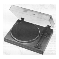
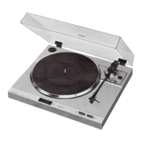
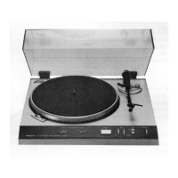
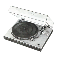
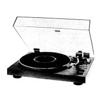
This document describes the Sanyo Plus Q50 Stereo Turntable, a full-auto, quartz-direct drive unit designed for high-fidelity audio playback. The manual provides detailed instructions for operation, maintenance, and repair, emphasizing the turntable's soft-touch digital controls and advanced motor control system.
The Sanyo Plus Q50 features a sophisticated control system based on digital circuits and soft-touch switches, offering a user-friendly interface for various functions. The control switches include start/stop, repeat, disc size selection (12", 10", and 7"), rotational speed adjustment (33 rpm and 45 rpm), quartz-lock, and cue.
The turntable's operation begins with an initialization sequence upon power-up. This sequence, managed by the INITIALIZE circuit (composed of C9, R13, and IC8), sets the initial state of all switches. During initialization, the cue and repeat functions are cleared, the disc size is set to 12", the rotational speed to 33 rpm, and the quartz circuit is locked.
Start/Stop Function: Pressing the start/stop switch (S14) activates a monostable multivibrator (IC1), which keeps the sub-motor drivers (Q1 and Q2) active for approximately two seconds. This initiates the sub-motor, allowing the arm to start its movement. Once the record playing concludes, the play (S13) and remain (S12) switches open, stopping the sub-motor.
Cue Function: The "cue" switch allows users to lift the tonearm during playback and lower it back to the same position. When pressed, the cue switch sends a signal to the monostable multivibrator (IC2), which generates a high-level output for 10 milliseconds. This output resets IC7, causing its Q output to go high, which in turn triggers the plunger driver (IC10) to activate the cue plunger (MG-3) and illuminate LED D1. Simultaneously, the other IC7 output (Q) goes low, activating plunger drivers Q8 and Q9 (Darlington circuit) for 8 to 9 seconds to maintain plunger driving. The Q side provides initial driving current, while the Q side holds the necessary current after the plunger is driven.
Rotational Speed Changing-Over: The turntable's rotational speed is initially set to 33 rpm during initialization. Users can switch to 45 rpm by pressing the 45 rpm switch. This action sends a signal to the S terminal (pin no. 4) of IC5, setting it and causing its output to go high. This turns off LED D2 and sets the main PCB's 33/45 rpm terminal to 45 rpm. The output also triggers the relay driver (IC10) to activate relay RL-2, which moves the relay terminal to the NO (normal open) side, enabling rotational speed adjustment (unless quartz-lock is active). LED D3 illuminates when the relay is driven. Pressing the 33 rpm switch resets IC5 via diode D11, returning the turntable to its initial 33 rpm setting.
Disc Size Changing-Over: The disc size is initially set to 12" during initialization. Users can change this to 10" or 7" using the respective switches. Pressing any of the three disc size switches (12", 10", or 7") sets IC5 through a selective circuit within IC3. For example, pressing the 10" switch sets IC5, raising its Q output to high. This triggers LED driver Q4, illuminating LED D5. The output then reaches the input terminal (pin no. 13) of NAND gate IC8, and IC5's Q output goes low at pin nos. 1 and 10, turning off D4 and D6. The output from pin no. 1 of IC5 also enters IC8's input terminal (pin no. 12), causing the cathode sides of D17 and D18 to go high, which triggers plunger driver IC10 to activate the plunger of MG-2, setting the disc size to 10". Diodes D17 through D20 prevent faulty operation and ensure the disc size is set to 12" if IC8 inputs are simultaneously high.
Repeat Function: During playback, pressing the "repeat" switch activates a monostable multivibrator (IC4), which generates a high-level output for approximately 10 milliseconds. This output sets IC6 via its CK terminal (pin no. 11), causing IC6's Q output to go high and trigger LED driver Q6, illuminating LED D7. When playback ends, the Q output goes low, fulfilling the requirements at NOR gate IC2, which initiates a repeat operation through diode D10. If the repeat switch is pressed before starting, pressing it again after about two seconds fulfills the requirements at the AND gate (diodes D13 and D14), resetting IC6 through its CL terminal (pin no. 11) and turning off LED D7. Subsequent presses of the repeat switch after two seconds will hold IC7, continuing the repeat operation after playback termination.
Quartz Locking: The "quartz-lock" switch is initially set during initialization. Pressing this switch feeds a signal to the monostable multivibrator (IC4), which generates a high-level output for approximately 10 milliseconds. This output sets IC6 via its CK terminal (pin no. 3), raising its Q output to high and triggering relay driver IC10 to activate relay RL-1. This moves the relay terminal to the NO (normal open) side, opening the quartz PLL terminal and the main-motor PCB's common terminal. This action cancels the lock and short-circuits the relay terminal of RL-2, enabling adjustment of VR1 (45 rpm) and VR2 (33 rpm).
Strobing: When the "power" switch (S10) is turned on and the "play" switch (S14) is closed, +B voltage is supplied to the motor PCB, driving the direct-drive motor. Simultaneously, the 4-stage binary counter within the motor PCB's ICO2 activates, and its output enters the monostable multivibrator (IC9). This switches Q11 of the LED driver on and off, causing D41 through D43 to flicker.
The Sanyo Plus Q50 is designed for ease of use with its soft-touch controls and automated functions. The full-auto operation simplifies the record playing process, making it accessible for all users. The ability to select disc size and rotational speed allows for playback of various record types. The cue function provides precise control over tonearm placement, while the repeat function offers continuous playback of a single record side. The quartz-lock feature ensures stable and accurate rotational speed, enhancing audio fidelity.
The manual provides clear instructions for several adjustments and repairs to ensure optimal performance and longevity of the turntable.
Adjustment of Auto-Return:
Adjustment of Lift-Up Lever Spring: With the power off and auto-return engaged, the spring tension should be adjusted to provide an 11 mm clearance between the stylus and the record. Turning screw (M6) clockwise will raise the lift-up lever.
Adjustment of Stylus Set Down: The lever (M43) shaft should be adjusted so that the needle descends at a position 147 mm from the center of a 12" record during auto play.
Adjustment of Headshell: The headshell should be level and not inclined. If necessary, loosen the two screws on the bottom of the tubular arm and adjust the headshell to ensure the stylus is normal to the record surface.
Adjustment of Tonearm Lifter: Depress the cueing button and turn screw (Y4) of the arm lifter (P) to adjust the distance between the stylus and the record surface to 9 mm when the stylus moves up near the outer circumference of the record.
Repair (Motor Lubrication): To maintain the direct-drive motor, dismount the turntable platter and apply two to three drops of oil into the D.D. motor through the hole in the motor housing. Care should be taken to avoid staining any exposed parts with oil to prevent operating trouble.
The schematic diagram for the D.D. motor circuit is provided as a reference. It is noted that if the circuit is impaired, the entire motor PWB assembly should be replaced rather than individual parts, as the circuit is factory-set for motor rotational speed and output torque.
| Drive method | Direct drive |
|---|---|
| Motor | DC servo motor |
| Wow and flutter | 0.025% WRMS |
| Signal to noise ratio | 75 dB |
| Overhang | 15 mm |
| Speeds | 33 and 45rpm |
| Tonearm | Statically balanced type |
| Cartridge | Not included |