Do you have a question about the Sanyo VCR 4500 and is the answer not in the manual?
| Tape Format | VHS |
|---|---|
| Heads | 2 |
| Audio | Mono |
| Timer | Yes |
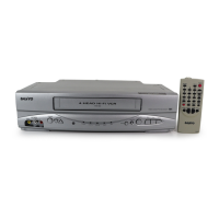
| Remote Control | Yes |
| Playback Speed | SP, LP |
| Tuner | Yes |
| Inputs | RF |
| Outputs | RF |
| Power Supply | 120V AC |
General safety guidelines and warnings for operating and servicing the VCR.
Procedure for checking AC leakage current to prevent electrical hazards.
Identifies the locations of various circuit boards within the VCR.
Details the removal procedure for the Video Circuit (VD-1).
Details the removal procedure for the Tuner Circuit (TN-2, TN-3).
Details the removal procedure for the System Control Circuit (SY-1).
Details the removal procedure for the Servo Circuit (SV-1).
Details the removal procedure for the Tuner and IF Circuit (TN-1).
Details the removal procedure for the Power Supply Circuit (PW-1, PW-2).
Details the removal procedure for the Antenna Terminal Board (TB-1).
Details the removal procedure for the System Control Circuit and Terminal Board (SY-2, TB-2).
Details the removal procedure for the Timer Circuit (TM-1).
Outlines required equipment and setup for circuit adjustments.
Specifies the alignment tape (VJ-0093) and its recorded signals.
Details checks for regulated voltage outputs in the power supply circuit.
Verifies DC voltage levels supplied to the System Control Circuit board.
Checks the functionality of the tape counter memory feature.
Verifies the VCR stops automatically when tape slack occurs.
Checks the unit's behavior upon reaching the end of the tape.
Confirms the correct operation of the front loading mechanism.
Confirms the correct operation of the front unloading mechanism.
Verifies the proper sequence of operations during Play mode.
Adjusts the reference voltage for the remote control system.
Sets the initial position for head switching.
Adjusts the Automatic Phase Control (APC) lock voltage.
Adjusts the head switching position during recording.
Adjusts the switching position for PG-A signal.
Adjusts the switching position for PG-B signal.
Adjusts APC lock voltage for Beta III mode.
Adjusts APC lock voltage for Beta II mode.
Adjusts the tape tracking for optimal playback.
Checks the control signal level during playback.
Adjusts the brake mechanism for still-frame operation.
Sets the timing for the still-frame brake engagement.
Adjusts the frequency response of the pre-amplifier.
Adjusts the dropout compensation sensitivity.
Adjusts the 3.58MHz oscillation frequency.
Adjusts the Automatic Gain Control (AGC) level.
Adjusts the comb filter for signal separation.
Sets the output level for the E-E (input-to-output) video signal.
Adjusts the Automatic Color Control (ACC) level.
Adjusts the 4.27MHz Band Pass Filter.
Minimizes carrier leakage in the chrominance signal.
Adjusts the Voltage Controlled Oscillator frequency.
Adjusts the noise canceller circuit.
Sets the playback level for the luminance signal.
Sets the recording current for the color signal.
Sets the recording current for the monochrome signal.
Adjusts sync tip carrier frequency and FM deviation.
Sets the vertical sync insert position for special playback.
Checks the +10V supply to the timer circuit.
Checks the -20V supply to the timer circuit.
Checks the filament voltage for the indicator tube.
Checks the frequency of the internal clock signal.
Checks the 60Hz clock signal timing.
Checks the reset input signal level.
Adjusts the Automatic Fine Tuning (AFT) for analog TV signals.
Fine-tunes the Automatic Fine Tuning (AFT) for VHF/UHF.
Adjusts the Radio Frequency Automatic Gain Control (RF AGC).
Lists specialized jigs and tools required for mechanism adjustments.
Procedure for cleaning or replacing the video head.
Instructions for cleaning audio/control and full-erase heads.
Instructions for cleaning or replacing the pinch roller.
Cleaning procedures for tape guides and drum tape path.
Procedure for removing and installing the supply reel base.
Procedure for replacing the audio/control head assembly.
Procedure for installing or replacing the forward (FWD) sensor.
Procedure for installing or replacing the rewind (REW) sensor.
Procedure for removing and installing the capstan motor.
Procedure for removing and installing the loading motor.
Procedure for removing and installing the loading ring.
Procedure for replacing the back tension brake band.
Procedure for removing and installing the reel motor.
Procedure for replacing the video head disc.
Procedure for replacing the slip roller assembly and belt.
Procedure for removing and installing the front loading motor.
Adjusts reel base height to ensure correct tape path.
Sets the back tension lever position for smooth tape travel.
Measures and adjusts winding torque for supply and take-up reels.
Adjusts the vertical position of the back tension guide.
Adjusts tape guides for the full-erase head.
Adjusts tape guides for the audio/control head.
Adjusts the tracking control for optimal signal reception.