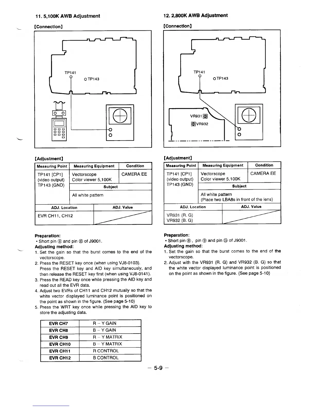
11.5,1 00K AWB Adjustment
r~mnnactinnl
---
. . . ..... . ... ...
—
L
L
I
R
00
D1
12. 2,800K AWB Adjustment
[Connection]
-––
TP141
F%
%
VR931 ❑
❑
VR932
m
o
—.- —.. —.. —.. —.. —
[Adjustment]
[Adjustment]
Meaauring Point Measuring Equipment
Condition
TP141 [CP1]
Vectorscope CAMERA EE
(video output)
Color viewer 5,1 00K
TP143 (GNDj
Subject
All white pattern
ADJ. Location ADJ. Value
EVRCH1l, CH12
Preparation:
● Short pin @ and pin @ of J9001.
Adjusting method:
1. Set the gain so that the burst comes to the end of the
vectorscope.
2. Press the RESET key once (when using VJ8-01 03).
Press the RESET key and AID key simultaneously, and
then release the RESET key first (when using VJ8-0141 ).
3. Press the READ key once while pressing the AID key and
read out all the EVR data.
4. Adjust two EVRS of CH11 and CH12 mutually so that the
white vector displayed luminance point is positioned on
the point as shown in the figure. (See page 5-1 O)
5. Press
the WRT key once while pressing the AID key to
store the adjusting data.
Measuring Point
Measuring Equipment
Condition
TP141 [CP1] Vectorscope CAMERA EE
(video output)
Color viewer 5,1 00K
TP143 (GND)
Subject
All white pattern
(Place two LBA8s in front of the lens)
ADJ. Location ADJ. Value
VR931 (R. G)
VR932 (B. G)
Preparation:
● Short pin @, pin @ and pin @ of J9001.
Adjusting method:
1. Set the gain so that the burst comes to the end of the
vectorscope.
2. Adjust with the VR931 (R. G) and VR932 (B. G) so that
the white vector displayed luminance point is positioned
on the point as shown in the figure. (See page 5-1 O)
EVR CH7
R – YGAIN
EVR CH8
B–YGAIN
EVR CH9
R - Y MATRIX
EVR CH1 O
B – Y MATRIX
EVR CHI 1
R CONTROL
EVRCH12
B CONTROL
– 5-9 –
 Loading...