2-12. POWER CIRCUIT
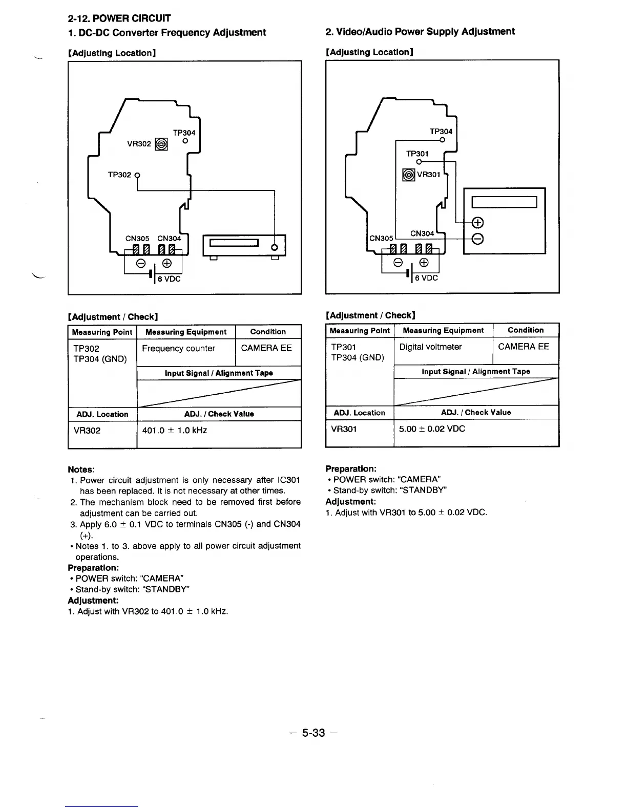
1. DC-DC Converter Frequency Adjustment
[Adlustlmi Locatlonl
—
“L
L
TP304
TP302
CN305 CN304
7
e,e
u
n
16 VDC
[Adjustment / Check]
Measuring Point
TP302
TP304 (GND)
ADJ. Location
VR302
Notes:
Measuring Equipment
Condition
Frequency counter CAMERA EE
I
Input Signal / Alignment Taps
I
ADJ. / Check Value
I
2. Video/Audio Power Supply Adjustment
[AdJusting Location]
[Adjustment / Check]
Measuring point I Measuring Equipment Condition
I
TP301
Digital voltmeter
CAMERA EE
TP304 (GND)
I
Input Signal / Alignment Tape
ADJ. Location
ADJ. / Check Value
VR301 5.oO & 0.02 VDC
401.0 f 1.0 kHz
I
Preparation:
1. Power circuit adjustment is only necessary after IC301
has been replaced. It is not necessary at other times.
2. The mechanism block need to be removed first before
adjustment can be carried out.
3. Apply 6.0 t 0.1 VDC to terminals CN305 (-) and CN304
(+).
s Notes 1, to 3. above apply to all power circuit adjustment
operations.
Preparation:
● POWER switch: “CAMERA
● Stand-by switch: “STANDBY
Adjustment:
1. Adjust with VR302 to 401.0 i
1.0 kHz.
● POWER switch: “CAMERA
● Stand-by switch: “STANDBY
Adjustment:
1. Adjust with VR301 to 5.00 + 0.02 VDC.
– 5-33 –
 Loading...