EasyManua.ls Logo

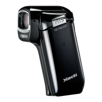
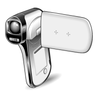
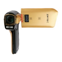
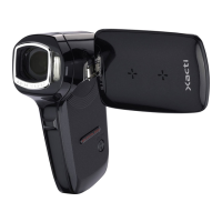
Sanyo VPC-CG11W - User Manual

Sanyo VPC-CG11W
59 pages
To Next Page IconTo Next Page
Loading...
FILE NO.
REFERENCE No.SM5310786
SG31B/U, U2, U3, EX, EX2, EX3, GX, GX2, GX3, PX, PX2, PX3
NOTE: 1. Parts order must contain model number, part number, and description.
2. Substitute parts may be supplied as the service parts.
3. N.S.P. : Not available as service parts.
Design and specifications are subject to change without notice.
SERVICE MANUAL
CONTENTS
1. OUTLINE OF CIRCUIT DESCRIPTION .....................................3
2. DISASSEMBLY ........................................................................12
3. ELECTRICAL ADJUSTMENT ..................................................17
4. USB STORAGE INFORMATION REGISTRATION ..................22
5. TROUBLESHOOTING GUIDE .................................................23
6. PARTS LIST .............................................................................24
CIRCUIT DIAGRAMS & PRINTED WIRING BOARDS ................C1
RoHS
This product does not contain any hazardous substances prohibited by the
RoHS Directive.
WARNING
You are requested to use RoHS compliant parts for maintenance or repair.
You are requested to use lead-free solder.
(This product has been manufactured using lead-free solder. Be sure to follow
the warning given on page 2 when carrying out repair work.)
CAUTION: Danger of explosion if battery is incorrectly replaced.
Replace only with the same of equivalent type recommended by the
manufacturer.
Discard used batteries according to the manufacturer's instruction.
Design and specifications are subject to change without notice.
VPC-CG11OR
(Product Code : 168 228 06)
VPC-CG11G
(Product Code : 168 228 10)
(U.S.A.) (Canada) (Taiwan)
VPC-CG11W
(Product Code : 168 228 02)
VPC-CG11EXG
VPC-CG11EXW
(Product Code : 168 228 03)
VPC-CG11EXOR
(Product Code : 168 228 07)
(Product Code : 168 28 11)
(Europe) (U.K.) (South America)
(China) (Australia) (Hong Kong)
(Russia) (Middle East) (Africa)
(General) (Korea) (Taiwan)
VPC-CG11GXG
(Product Code : 168 228 12)
(South America) (China) (Australia)
(Hong Kong) (General) (Korea) (Taiwan)
VPC-CG11GXW
(Product Code : 168 228 04)
VPC-CG11GXOR
(Product Code : 168 228 08)
VPC-CG11PXG
(Product Code : 168 228 15)
(General)
VPC-CG11PXW
(Product Code : 168 228 13)
VPC-CG11PXOR
(Product Code : 168 228 14)
Question and Answer IconNeed help?

Do you have a question about the Sanyo VPC-CG11W and is the answer not in the manual?

Sanyo VPC-CG11W Specifications

General IconGeneral
Optical Zoom5x
Digital Zoom12x
Sensor TypeCMOS
DisplayLCD
StorageSD/SDHC
Display TypeLCD
MicrophoneStereo
Supported Flash MemorySD/SDHC
Video FormatMPEG-4 AVC/H.264
Image FormatJPEG
Battery TypeLithium-Ion
Optical Sensor Size1/2.3-inch
Image StabilizerElectronic
Shooting ModesAuto, Scene
Display Size2.7 inches
Connector TypeUSB, HDMI
LCD Screen Size2.7 in
Storage MediaSD/SDHC

Summary

Outline of Circuit Description

CMOS Circuit Description

Details the CMOS imaging circuit, including IC configuration and pixel array.

System Circuit Descriptions

CP1 and VF1 Circuit Description

Covers digital clamp, signal processing, AE/AWB/AF, SDRAM, and communication circuits.

Lens Drive Block

Details the mechanism and control for lens focusing, zooming, iris, and shutter operations.

Video Clip Recording and Playback

Outlines the process of recording and playing back video clips, including audio.

PWA Power Circuit Description

Provides an overview of the main power circuit and its constituent blocks.

ST1 Strobe Circuit Description

Explains the charging and light emission circuits for the strobe.

SYA Circuit Description

Describes the SYA block's configuration and the functions of its 8-bit microprocessor.

Power Supply Control

Explains how the 8-bit microprocessor manages the system's power supply.

Disassembly and Board Location

Disassembly Procedures

Guides for removing external components and internal boards like ST1, CP1, TB1, VF1.

Board Location Overview

Illustrates the physical placement of major circuit boards within the camera.

Electrical Adjustments

Servicing Tools and Setup

Lists necessary tools, software, system requirements, and initial setup for adjustments.

Adjustment Procedures

Covers lens focus, AWB, CCD defect detection, factory code, and language settings.

Firmware Update

Guides on how to update the camera's firmware via SD card or software.

Troubleshooting and Parts List

Troubleshooting Guide

Provides diagnostic flowcharts for common camera malfunctions.

Parts List

Catalog of replacement parts, including packing materials and accessories.

Cabinet and Chassis Parts

Details components related to the camera's structural housing.

Circuit Diagrams and Wiring Boards

Overall Wiring and Block Diagrams

Presents high-level wiring and block diagrams of the camera system.

Circuit Diagrams

Contains detailed schematics for various circuit sections of the camera.

Printed Wiring Boards (P.W.B.) Layouts

Shows the physical layout of the printed wiring boards for different modules.

Related product manuals